 Skip to content
 About X7 Series Intelligent Controllers
The X7 series Controller is independently designed by CUAV and developed in cooperation with two international UAS open-source platforms, Ardupilot and PX4. It is aimed primarily at the industrial or commercial drone market.
among them:
X7+ Pro: A separate design allows users to DIY their own baseboard.
Nora+: integrated design, side interface, small size.
X7+: Modular design, customizable carrier board.
| X7 | X7+ | X7 Pro | X7+ Pro | Nora | Nora+ | |
| Processor | STM32H743 | STM32H743 | STM32H743 | STM32H743 | STM32H743 | STM32H743 |
| Grro/ACC | BMI088 | ICM42688-P | ADIS16470 | ADIS16470 | BMI088 | ICM42688-P |
| ICM20689 | ICM20689 | BMI088 | ICM42688-P | ICM20689 | ICM20689 | |
| ICM20649 | ICM20689 | ICM20649<br/ | ICM20689 | ICM20649 | ICM20689 | |
| Compass | RM3100 | RM3100 | RM3100 | RM3100 | RM3100 | RM3100 |
| barometer | MS5611 | MS5611 | MS5611 | MS5611 | MS5611 | MS5611 |
| PWM output | 14 | 14 | 14 | 14 | 14 | 14 |
| DBSTOT channel | 4(M9~M12) | 12(M1~M12) | 4(M9~M12) | 12(M1~M12) | 4(M9~M12) | 12(M1~M12) |
| Servo voltage monitor | NO | YES(9.9V max) | NO | YES(9.9V max) | NO | YES(9.9V max) |
| Operating Voltage | 4.3~5.4V (USB:4.75~5.25V) | 4.3~5.4V (USB:4.75~5.25V) | 4.3~5.4V (USB:4.75~5.25V) | 4.3~5.4V (USB:4.75~5.25V) | 4.3~5.4V (USB:4.75~5.25V) | 4.3~5.4V (USB:4.75~5.25V) |
| Power monitor | 2 | 2 | 2 | 2 | 2 | 2 |
| Baseboard | YES | YES | YES | YES | NO | NO |
X7+ Controller
X7+® is an advanced Controller independently designed by CUAV®. It uses a higher-performance STM32H7 processor and integrates industrial-grade sensors. Compared with the previous flight controller, it has better performance and more reliability. This board can run ArduPilot firmware perfectly, and it will also be compatible with PX4 firmware. X7+ is ideal for academic research and commercial systems integration.

Note
The X7+ autopilot is a derivative version of the X7 autopilot. Some sensors have been changed and the built-in shock absorption has been optimized; it is compatible with ArduPilot 4.1.0/PX4 v1.12.3 and above firmware.
Other characteristics
- Internal shock absorption
- Modular design, can be a DIY carrier board
- Support more dshot output
- Support IMU heating, make the sensor work better
- Dedicated UAVCAN battery port
- 3 sets of IMU sensors
- High-performance ICM-42688-P sensor
Quick Summary
- Main FMU Processor: STM32H743
On-board sensors:
- Accelerometer/Gyroscope: ICM-42688-P(X7:BMI088)
- Accelerometer/Gyroscope: ICM-20689
- Accelerometer/Gyroscope: ICM-20689(X7:ICM-20649)
- Magnetometer: RM3100
- Barometer: MS5611*2
Interfaces:
- 14 PWM outputs (12 support Dshot)
- Support multiple RC inputs (SBUs/CPPM/DSM)
- Analogue/ PWM RSSI input
- 2 GPS ports(GPS and UART4 ports)
- 6 i2c buses(4 independent i2c interfaces, 2 integrated in GPS and UART4 interface)
- 2 CAN bus ports
- 2 Power ports(Power A is common adc interface, Power C is uavcan battery interface)
- 1 ADC input
- 1 USB port
- Power System:
- Power: 4.5~5.4V
- USB Input: 4.75~5.25V
- Servo Rail Input: 0~10V
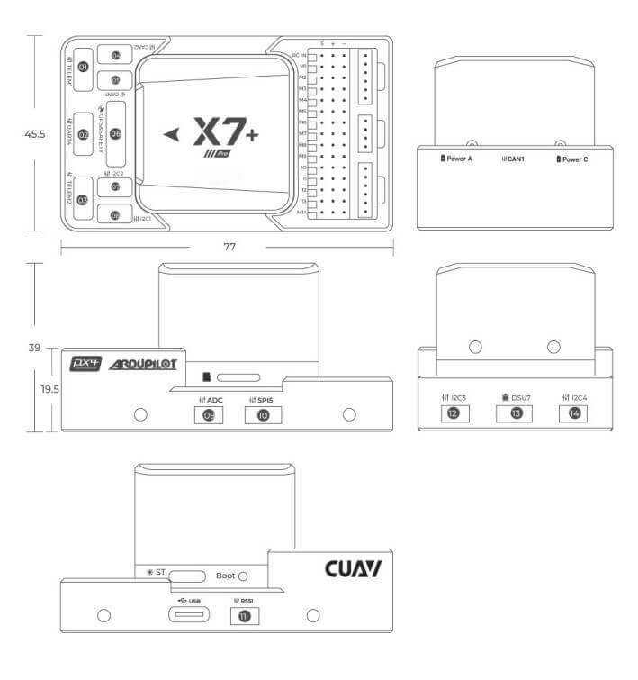
- Weight and Dimensions:
- Weight: 101 g
Other Characteristics:
- Operating temperature: -20 ~ 85°c
- Three imus
- Supports temperature compensation
- Internal shock absorption
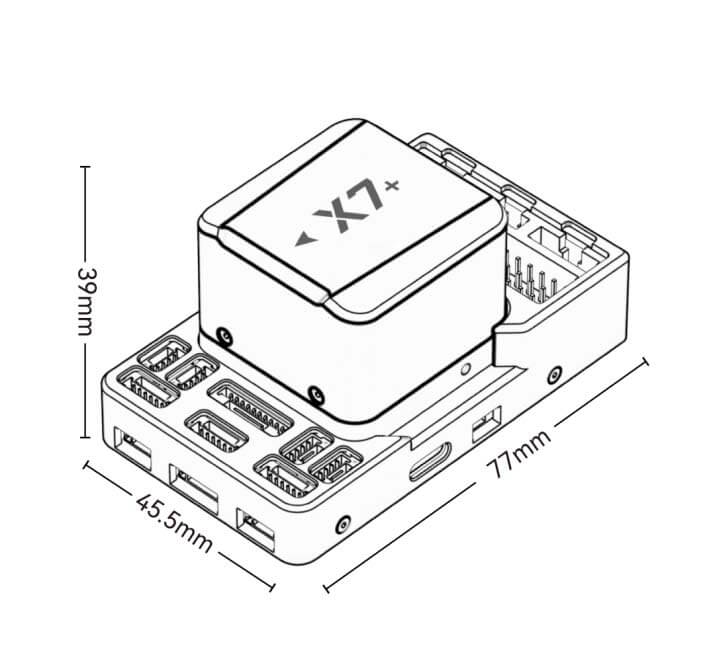
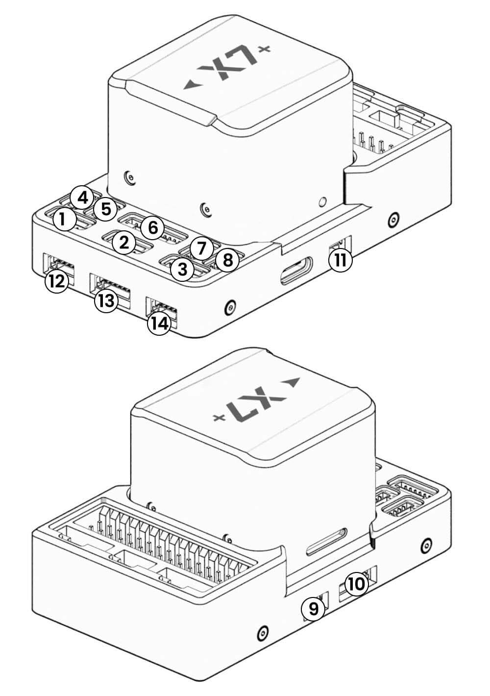
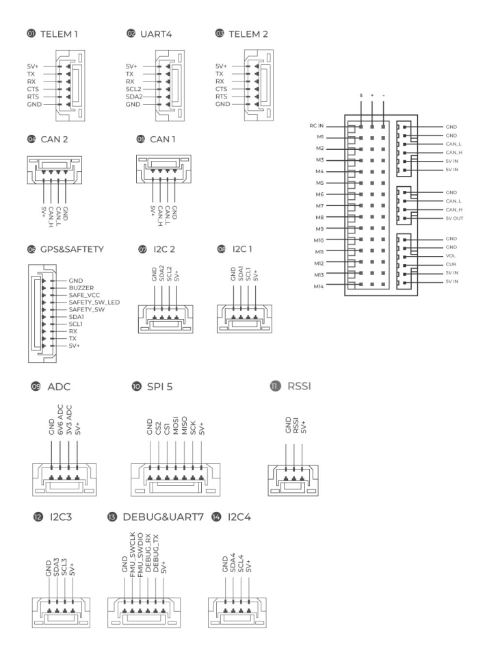
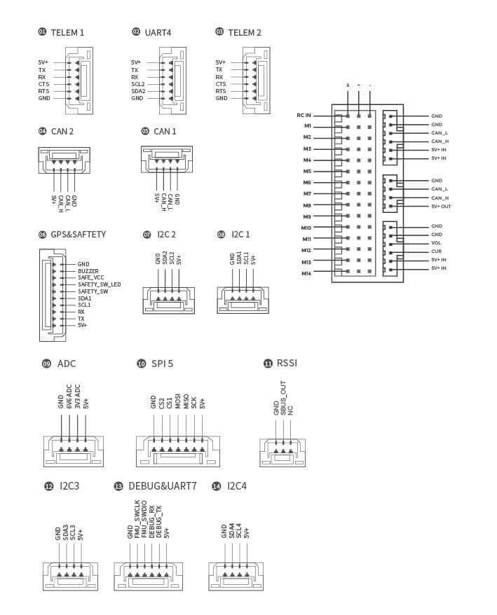
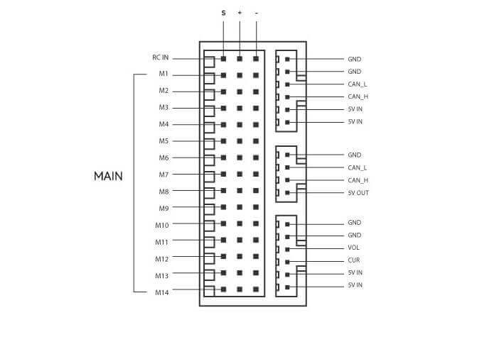
Size and Pinouts
Warning
The RCIN port is limited to powering the rc receiver and cannot be connected to any power/load.
Voltage Ratings
- The X7+ controller can be triple-redundant on the power supply if three power sources are supplied. The two power rails are: POWERA, POWERC, and *USB.
Warning
The output power rails PWM OUT (0V to 10V) do not power the controller board (and are not powered by it). You must supply power to one of POWERA, POWERC or USB or the board will be unpowered.
Normal Operation Maximum Ratings
Under these conditions, all power sources will be used in this order to power the system:
- POWERA and POWERC inputs (4.5V to 5.4V)
- USB input (4.75V to 5.25V)
Debug Port
The system’s serial console and SWD interface operate on the DSU7 port. Simply connect the FTDI cable to the DSU7 connector (the product list contains the CUAV FTDI cable).
Peripherals
- Digital Airspeed Sensor
- Telemetry Radio
- Rangefinders/Distance sensors
- others
Firmware
You can choose to use ArduPilot (recommended)/PX4 firmware.
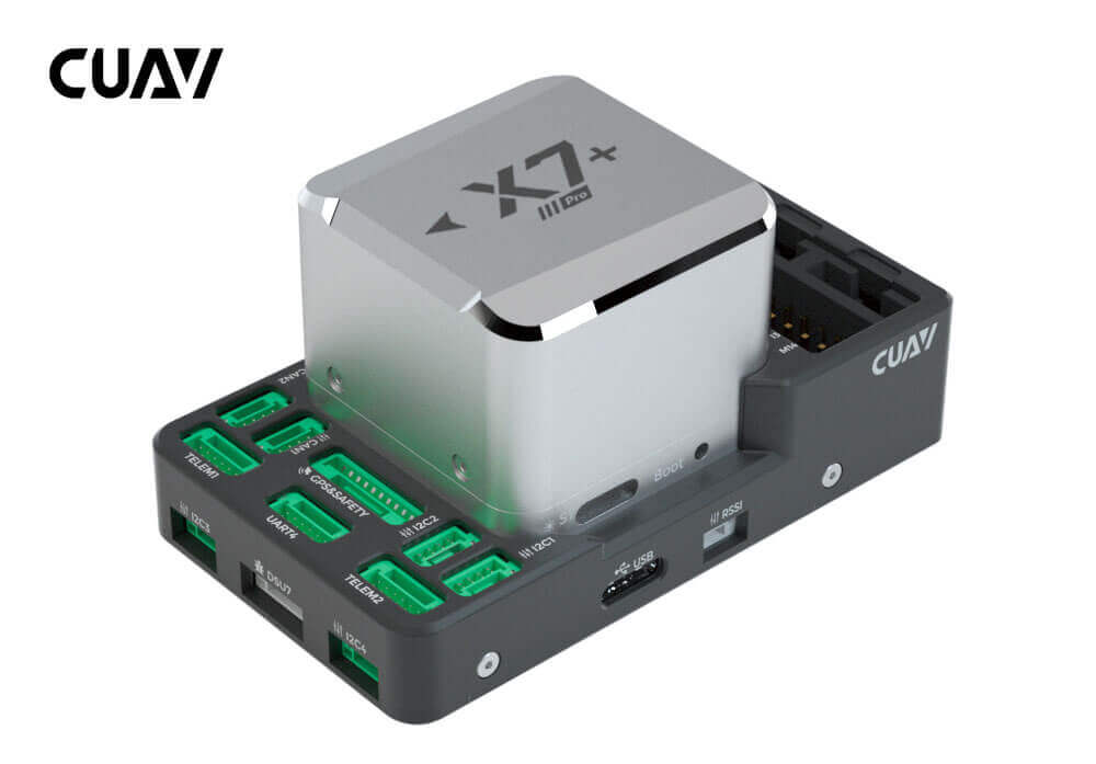
X7+ Controller
X7+ Pro is a high-end intelligent controller developed by CUAV® for industry and industrial applications. It is equipped with a high-performance STM32H7 processor with a processing speed of up to 480Mhz and supports double floating-point operations. It is also equipped with an ADIS16470 automotive-grade sensor with excellent gyroscope and accelerometer performance, supports low-error long-flight attitude calculation, and is equipped with an industrial-grade RM3100 magnetometer, which has strong anti-magnetic interference capabilities. The excellent processor performance and IMU performance enable unmanned system equipment to have better stability and anti-interference capabilities in complex environments.
Tip
X7+ Pro autopilot is a derivative version of X7 Pro. From January 1, 2022, X7+ Pro will replace X7 Pro; X7+ Pro is perfectly compatible with ArduPilot 4.10/PX4 V1.12.3 and higher firmware.X7+ Pro supports monitoring Servo port voltage, the maximum input voltage of Servo port is 10V; other parts have no difference.
Other characteristics
- The automotive-grade ADIS16470 gyroscope and accelerometer provide long-term stable and accurate dead-position attitude estimation.
- Industrial-grade RM3100 magnetic compass, with significant anti-magnetic interference capability
- New generation CUAV patented shock absorption, better shock absorption effect
- Three sets of IMU support fault intelligent switching
- Support temperature compensation, the IMU working condition is better
- Modular design, support customized carrier board
- Dedicated Dronecan power interface
Quick Summary
- Main FMU Processor: STM32H743
On-board sensors:
- Accelerometer/Gyroscope: ICM42688-P(X7 Pro:ICM-20649)
- Accelerometer/Gyroscope: ADIS16470
- Accelerometer/Gyroscope: ICM20689-P(X7 Pro:BMI088)
- Magnetometer: RM3100
- Barometer: MS5611*2
Interfaces:
- 14 PWM outputs (12 support Dshot)
- Support multiple RC inputs (SBUs/PPM/DSM)
- Analogue / PWM RSSI input
- 2 GPS ports(GPS and UART4 ports)
- 6 i2c buses( 4 independent i2c interfaces, 2 integrated in GPS and UART4 interface)
- 2 CAN bus ports
- 2 Power ports(Power A is common adc interface, Power C is uavcan battery interface)
- 2 ADC input
- 1 USB port
- Power System:
- Power: 4.5~5.4V
- USB Input: 4.75~5.25V
- Servo Rail Input: 0~10V
- Weight and Dimensions:
- Weight: 101g
- Other Characteristics:
- Operating temperature: -20 ~ 85°c
- Three imus
- Supports temperature compensation
- Internal shock absorption
Quick Summary
Warning
The RCIN port is limited to powering the rc receiver and cannot be connected to any power/load.
Voltage Ratings
- Nora AutoPilot can be triple-redundant on the power supply if three power sources are supplied. The two power rails are: Power A, Power C, and *USB.
Note
The output power rails PWM OUT (0V to 10V) do not power the flight controller board (and are not powered by it). You must supply power to one of Power A, Power C or USB or the board will be unpowered.
Normal Operation Maximum Ratings
Under these conditions, all power sources will be used in this order to power the system:
- POWERA and POWERC inputs (4.5V to 5.4V)
- USB input (4.75V to 5.25V)
Building ArduPilot Firmware
./waf configure --board CUAV-x7
./waf copter --upload
Debug Port
The system’s serial console and SWD interface operate on the DSU7 port. Simply connect the FTDI cable to the DSU7 connector (the product list contains the CUAV FTDI cable).
Peripherals
- Digital Airspeed Sensor
- Telemetry Radio
- Rangefinders/Distance sensors
- others
X7/X7+ Wiring Quick Start
This quick start guide shows how to power the X7+ controller and connect its most important peripherals.
Tip
This chapter applies to X7 and X7+ controllers.
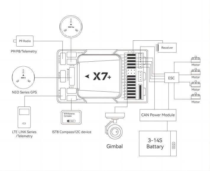
Wiring Chart Overview
The image below shows how to connect the most important sensors and peripherals (except the motor and servo outputs). We’ll go through each of these in detail in the following sections.
Main interface | Function |
| POWER A | Connect the power module. Power input with analog voltage and current detection. Do not use a Digital PM on this connector! |
| POWER C | Please connect CAN PMU SE to this interface; this interface is connected to the Dronecan power module |
| GPS&SAFETY | Connect Neo series GPS or C-RTK 9P, including GPS, safety switch, buzzer interface. |
| UART 4 | Can be used to connect to GPS, can be used as a second GPS |
| TELEM1/TELME2 | Connect to the Telemetry System |
| TF CARD | SD card for log storage (card pre-inserted in factory). |
| M1~M14 | PWM signal output port, which can be used to control motors or steering gears; and M1~M12 also support DShot protocol |
| DSU7 | Used for FMU chip debugging, read the DEBUG device information |
| TYPE-C(USB) | Connect to a computer for communication between the flight controller and the computer, such as loading firmware. |
| I2C1/I2C2/i2C4 | Connect an I2C device, such as an external compass. |
| CAN1/CAN2 | Connect Dronecan devices, such as CAN GPS. |
| RC IN | Including DSM, SBUS, RSSI signal input interface, DSM interface can be connected to DSM satellite receiver, SBUS interface to connect SBUS remote control receiver |
| RSSI | RSSI for the signal strength return module |
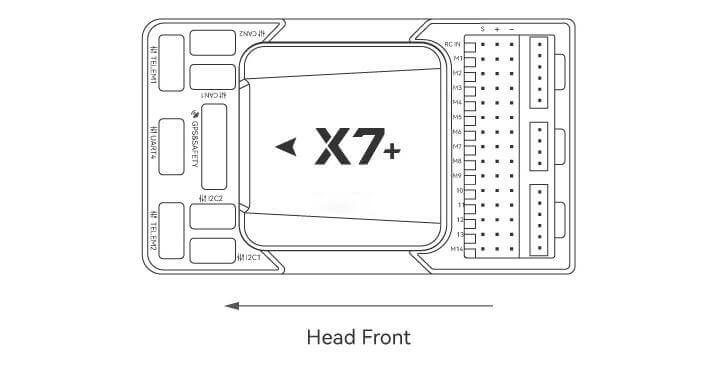
Vehicle Front
Tip
If the controller cannot be mounted in the recommended/default orientation (e.g. due to space constraints) you will need to configure the autopilot software with the orientation that you actually used: Flight Controller Orientation.(for PX4 firmware, for Ardupilot firmware).
GPS
We recommend that you use UAVCAN GPS/RTK (such as Neo 3 pro); you only need to connect it to the CAN 1/2 interface; you can also use an ordinary GPS/RTK module; connect it to the GPS interface; it is commonly used now The GPS module generally integrates GPS, compass, safety switch, buzzer, and LED status light. The GPS module should be installed on the bracket and far away from other electronic devices. The installation direction is towards the front of the carrier (the NEO GPS arrow is in the same direction as the flight control arrow)
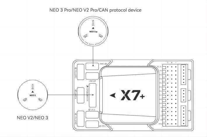
Tip
X7+ may not be fully compatible with ordinary GPS modules of other manufacturers. If you need to use ordinary GPS, please choose NEO V3; for a better experience, we recommend you to use UAVCAN GPS.
safety switches
Tip
When you use NEO series GPS, there is no need to install additional safety switches.
If you are flying without GPS, you must connect the switch directly to the GPS1 port to be able to arm and fly the drone. (If you use the old 6-pin GPS, please check the interface definition at the bottom to change the line.)
Buzzer
Tip
When you use NEO series GPS, there is no need to install additional Buzzer.
If you use other manufacturers’ GPS, the buzzer may not work.
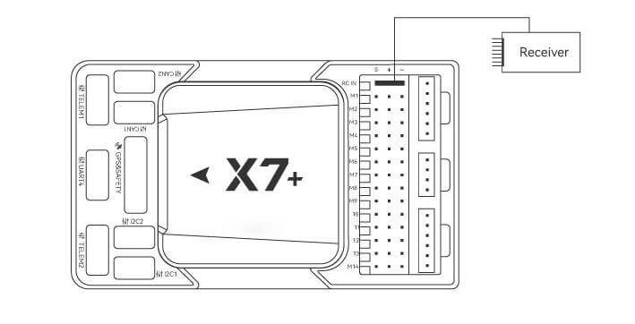
Radio Control
For your flight safety, it is recommended that whether you fly manually or automatically, please connect the handheld remote control (it can be used as an emergency machine, unless you are not proficient in operating the handheld remote control).
The figure below shows how you can connect to your remote control receiver (please find the Dupont cable in the package)
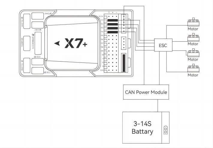
Power
X7+ is equipped with a CAN PMU SE module, which supports a 3~14s lithium battery. Please connect the 6-pin connector of the module to the flight control Power C interface
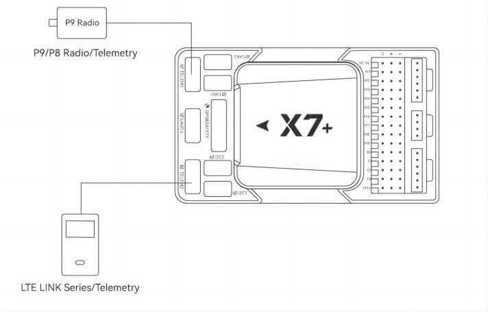
Telemetry (Radio) system
Using the telemetry system, you can communicate with the drone through the ground station software. Monitor and control drones in flight. The airborne end of the telemetry system should be connected to the TELEM1/TELEM2 interface.
SD Card
The SD card is already installed on X7+ when it leaves the factory, so you don’t need to install it.
Motors/Servo
The motor/servo system is connected to the M1~M14 ports in the order specified for your carrier in the fuselage reference.
Servo power supply
The servo interface of X7+ is completely isolated from the internal power supply of the controller. The controller will not supply power to the steering gear. If you need to supply power to the steering gear, please connect the BEC to any of the positive and negative stages of M1~M14 (M1~M14). The positive and negative times of the two are connected. Then connect the Servo.
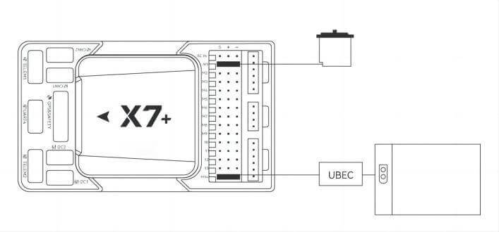
Tip
X7+ supports monitoring servo input voltage, maximum support 10v.
