 Skip to content
 C-RTK 2 PPK: Specs, Quick Start, Parameters & Firmware
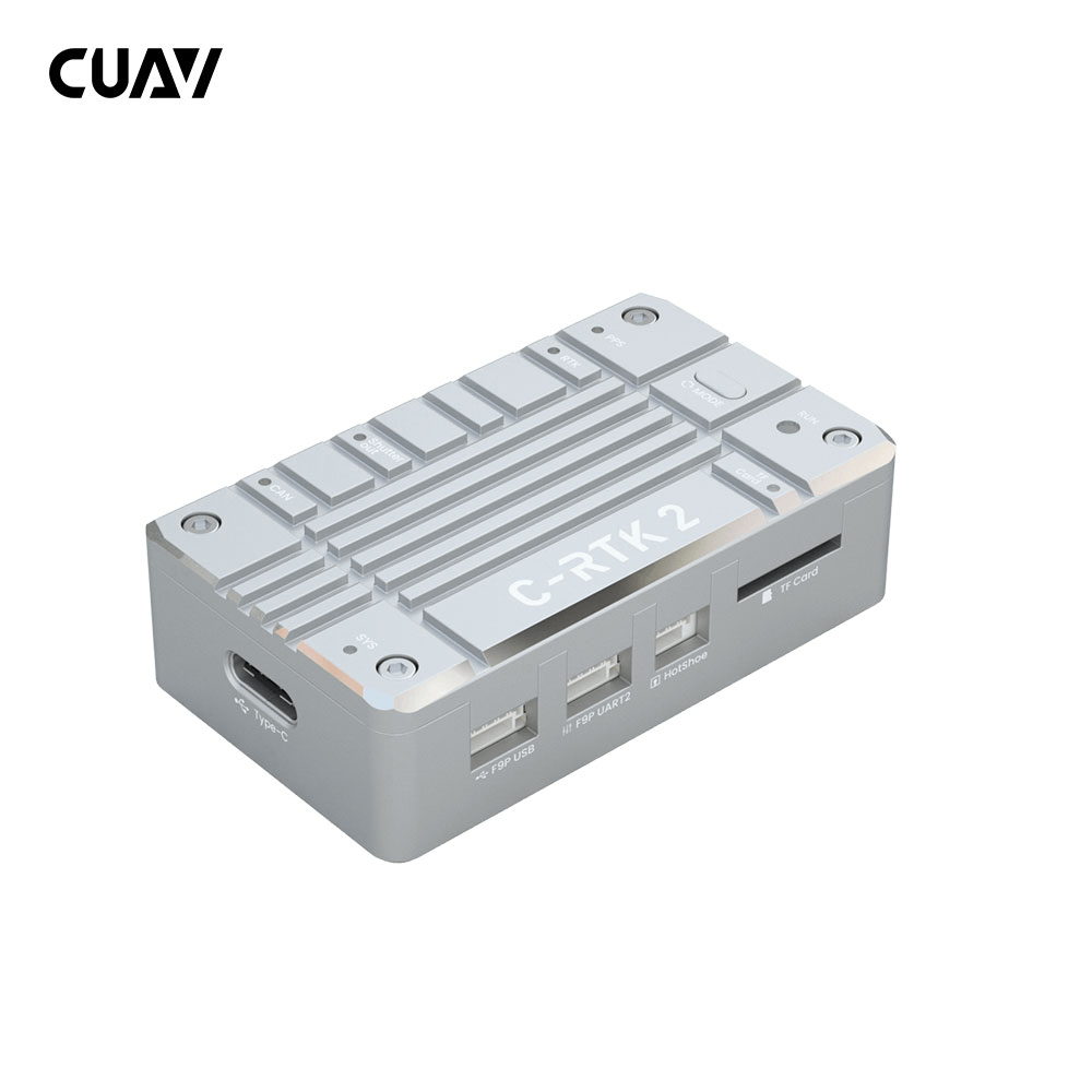
C-RTK 2 is a high-performance PPK/RTK positioning module created by CUAV for professional applications such as drone aerial survey (Mapping); its lightweight shape, industrial-grade IMU combination, and clever combination of high-precision positioning modules can easily cover Various specifications of Copter/VTOL/Helicopter, etc.
Other Characteristics
- High-performance H7 processor
- High precision industrial grade IMU
- Support RTK and save the raw data (PPK) at the same time
- Multi-satellite and multi-frequency receivers
- UAVCAN/Dronecan protocol
- Support hotshoe and shutter trigger
- Perfectly compatible with ArduPilot/PX4 flight controller, with X7 series flight controller, it can be plug and play.
- HS_USB and U disk mode
Quick Summary
- RTK Receiver
- ZED-F9P
- Receiving channel
- 184
- Main FMU Processor
- STM32H743VIH6(2M flash、1M RAM)
- On-board sensors:
- Accelerometer/Gyroscope: ICM20689
- Magnetometer: RM3100
- Barometer: ICP10111
- TF card expansion
- 32G(MAX)
- PPK(post processed kinematic)
- support
- RTK(Real – time kinematic)
- support
- GNSS Bands
- GPS:L1C/A,L2C
- GLONASS:L1OF,L2OF
- GALILEO: E1B/C E5b
- Beidou: B1I B2I
- Enhanced system
- QZSS:L1C/A,L2C,L1S
- SBAS: L1C/A
- Number of concurrent GNSS
- 4(GPS、GLONASS、GALILEO、Beidou)
- Nav. update rate
- RTK Up to 20Hz
- RAW Up to 25Hz
- default:5hz
- Convergence time
- RTK < 10 sec
- Position accuracy(RMS)
- RTK:0.01m+1ppm(level);0.02m+1ppm(vertical)
- GPS:1.5m(level)
- Acquisition
- Cold starts 24 s
- Aided starts 2 s
- Reacquisition 2 s
- Sensitivity
- Tracking & Nav –167 dBm
- Cold starts –148 dBm
- Hot starts –157 dBm
- Reacquisition –160 dBm
- Anti-spoofng
- Advanced anti-spoofing algorithms
- Protocols
- NMEA
- UBX binary
- RTCM version 3.x
- Time pulse
- 0.25Hz~10Hz(Configurable)
- Anti-jamming
- Active CW detection and removal, Onboard band pass flter
- Support flight control type
- Compatible with flight controllers running ArduPilot/PX4 firmware
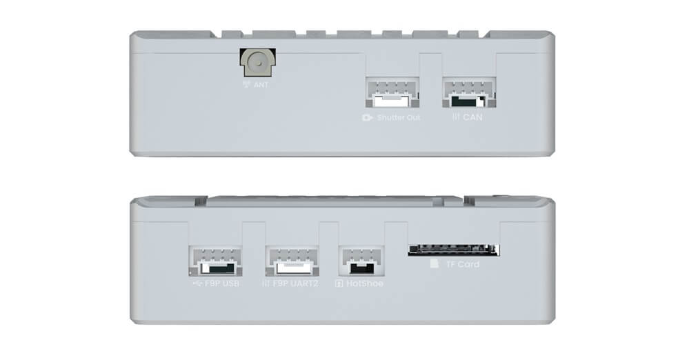
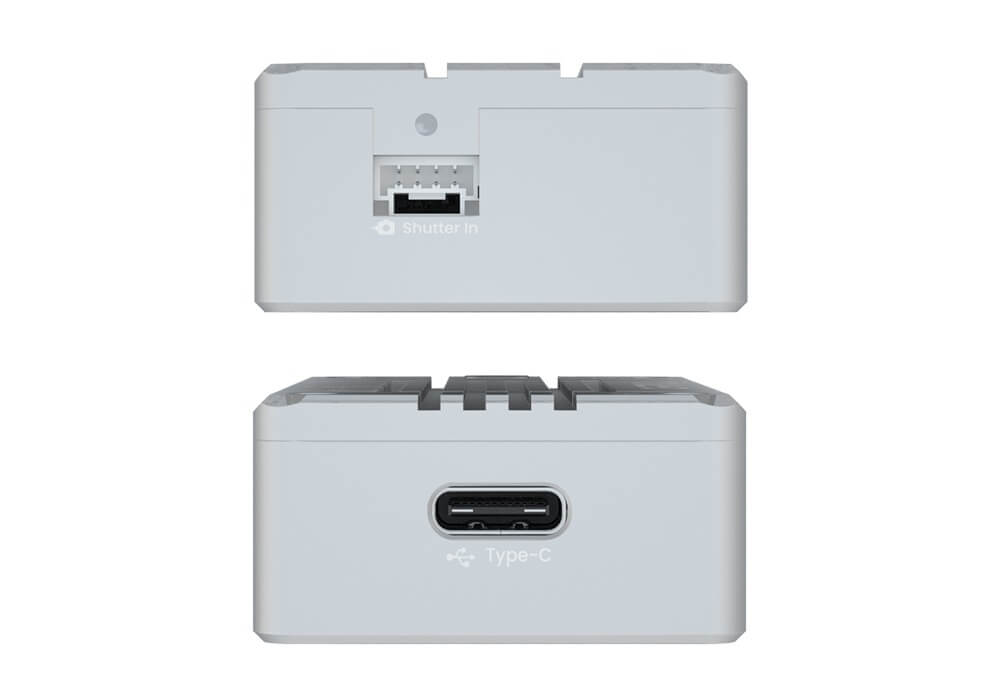
- interface
- 1 Hotshoe
- 1 shutter in
- 1 sutter out
- 1 Type(HS_USB)
- 1 F9P USB
- 1 F9P UART
- 1 Antenna(mmcx)
- Supply voltage
- 4.5~6v
- Operating temperature
- -20~85℃
- Size
- 56x33x16.5mm
- Weight
- 39g
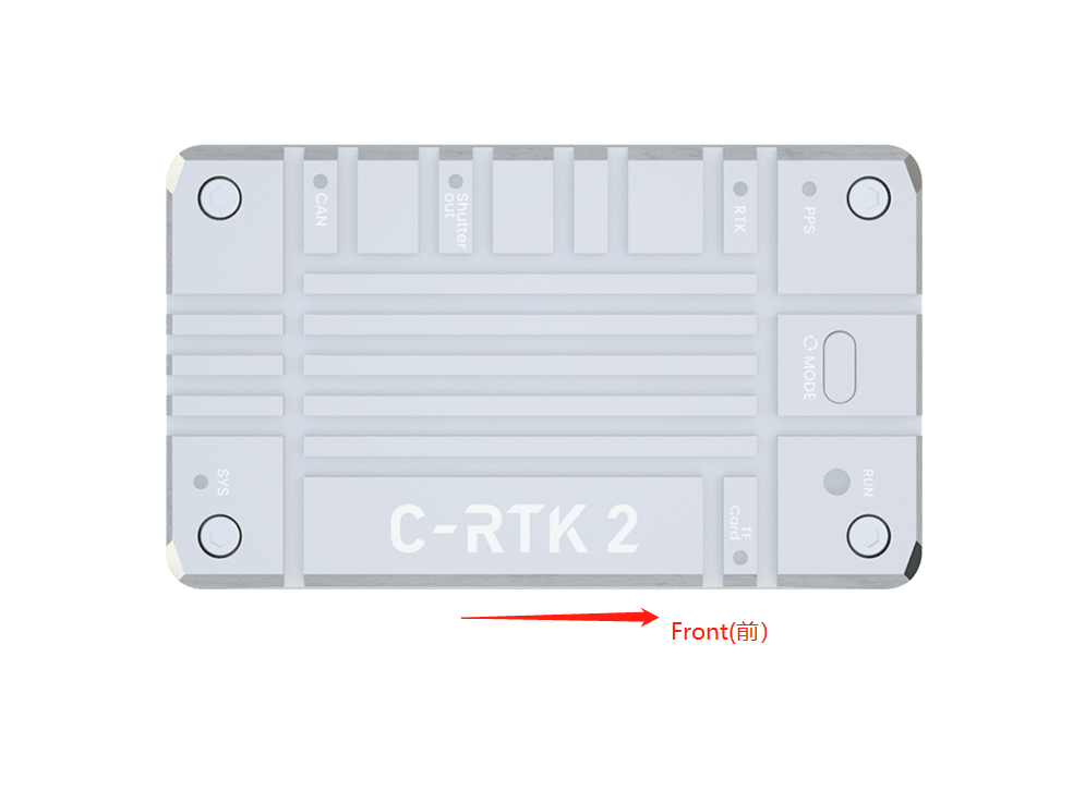
LED implication
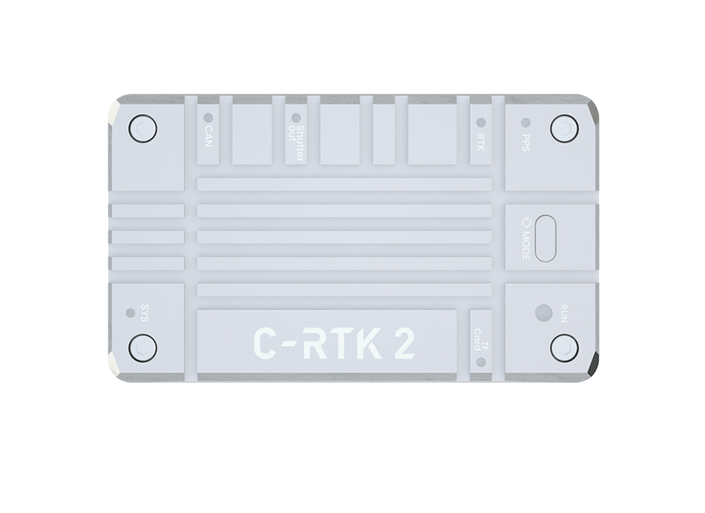
- SYS Led
- 100ms flashing: Stay in bootloader
- 1000ms flashing: Normal working condition
- TF LED(TF Card)
- Flashing: SD card reading and writing are normal
- Always bright: No TF card or file system error on the TF card. You can try to restart the power.
- Shutter in led
- Flashing: Camera shutter signal input
- Shutter out led
- Flashing: Output shutter trigger signal to the camera
- CAN LED
- Always went out: No data input or output
- Blink once every 2 seconds: Only data is sent, but no data is received
- Blink twice within 2 seconds: only data is received, but no data is sent
- Blink 3 times in 2 seconds: send and receive data.
- PPS LED
- Always bright: no FIX
- flash: FIX
- RTK LED
- Blink 3 times in 2 seconds: send and receive data.
- Flash: RTK Float
- Always bright: RTK FIX
- Always went out: NO RTK
RUM LED
- Red LED is always bright: system error
- Yellow led always bright: application warning
- Yellow flashing (100ms):GNSS(F9P) firmware update
- Blue Flashing: base station mode
- Green Flashing: Rover
Mode button
- When not connected to the computer, press and hold for 3 seconds to switch the mode
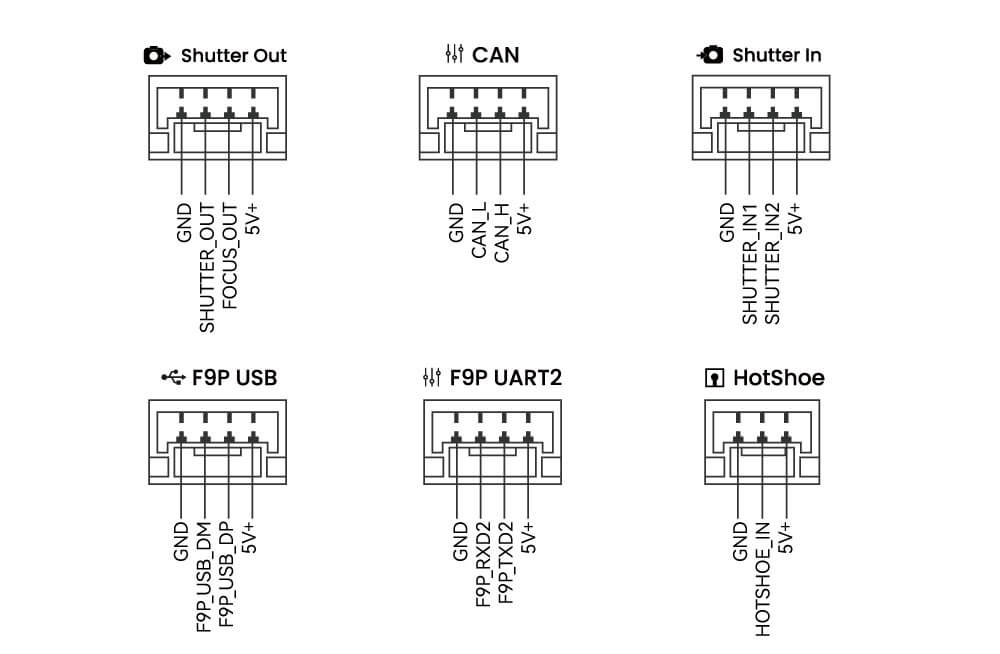
Pinouts
Video
C-RTK2 Quick start
This section introduces how to configure and use C-RTK 2 quickly.
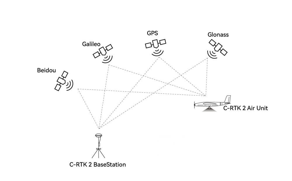
Build an aerial survey system
According to your different needs, you need to prepare the following equipment first.
Only Use PPK
According to your different needs, you need to prepare the following equipment first

- PPK base station/Ntrip account *1
- C-RTK 2 *1
- Mapping camera *1
- Drone *1
PPK+RTK
- PPK base station/Ntrip account *1
- C-RTK 2 *1
- Mapping camera *1
- Drone *1
- Data link *1
- Computer *1
Note
C-RTK 2 is used as an RTK base station and rover station, as well as a PPK rover station,It is not recommended to be used as a PPK base station.
Hardware Connection
According to different camera types, there are different connection methods
Five-lens mapping camera/DIY method
- Use a cable to connect the flight controller and C-RTK2 (communication and power supply)
- Use the hot shoe cable to connect to the hot shoe cable of the five-lens camera
- The shutter trigger pin of the flight control is connected to the five-lens camera shutter cable
Canon/Sony cameras and other cameras with hotshoes
- Use a cable to connect the flight controller and C-RTK2 (communication and power supply)
- Use the hotshoe cable to connect to the hotshoe PCB and C-RTK Hotshoe interface, and insert the PCB into the camera hot shoe interface
- The shutter trigger pin of the flight control is connected to the Shutter in the interface
- C-RTK2 Shutter out is connected to the camera shutter interface
Note
The above is the recommended method of use. You can also use it with a camera without hot shoe feedback and use the shutter trigger to record the POS; but you may need to tolerate the accuracy error caused by the delay.
Camera without hot shoe (shutter trigger recording pos)
Note
For some special cameras without hot shoe feedback, C-RTTK supports the use of shutter trigger to record POS; but due to various reasons, there is an error (delay) between the camera and POS recording time; it may affect the accuracy of aerial survey; when using this method The C-RTK 2 parameter CAM_FEEDBACK_TYPE needs to be set to 0.
- Use the CAN cable to connect the flight controller and the CAN (communication and power supply) of the C-RTK2.
- The shutter trigger pin of the flight controller is connected to the Shutter in the interface
- C-RTK2 Shutter out is connected to the camera shutter port
Install to rone
Note
The direction of the device should be consistent with the direction of the aircraft; otherwise, you may need to configure additional flight control parameters
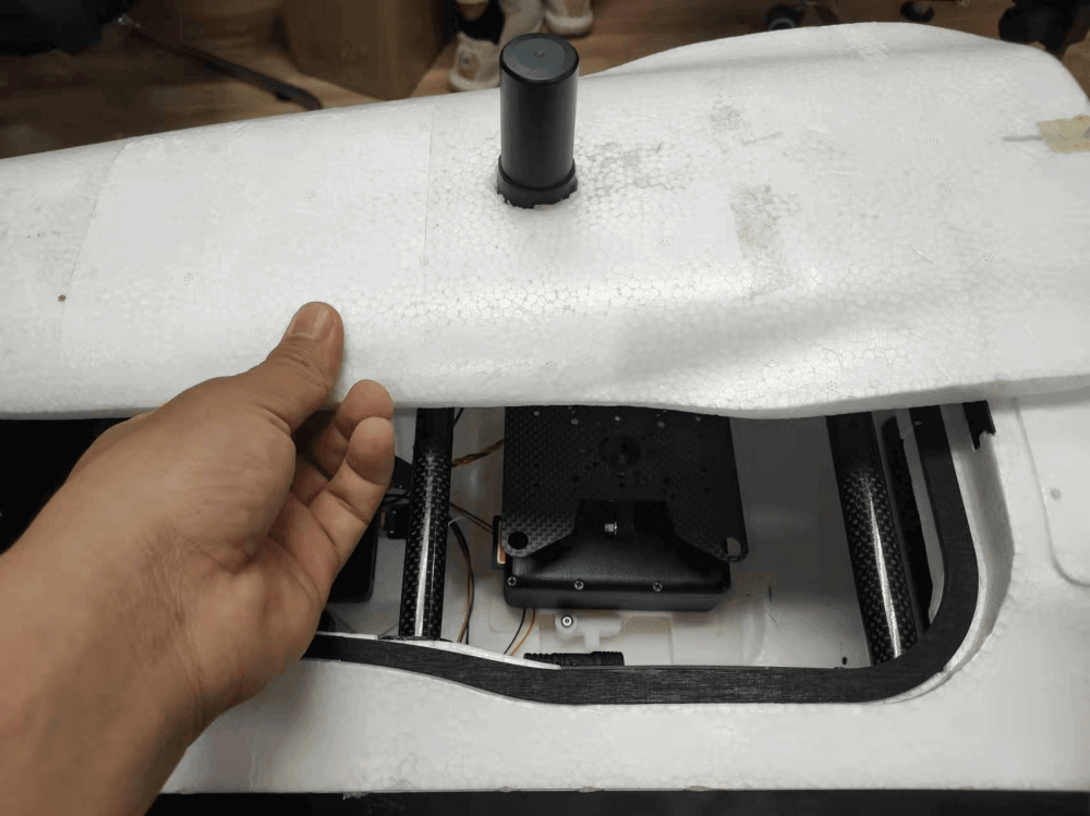
Note
It is recommended to install the C-RTK2 antenna directly above the camera to avoid configuring the antenna offset.
Set flight control parameters
Depending on the flight controller firmware, the set parameters are different. The following is the setting guide for ArduPilot/PX4 firmware. If you use other flight controllers, please refer to the relevant controller shutter setting guide; the following configuration uses a common relay/level shutter Trigger as an example, and also supports PWM shutter trigger.
ArduPilot
Note
The flight control parameters are set in MissionPlanner》Configuration》All parameter table/parameter tree. After modification, please click the write button on the right side and restart the flight control.
Enable UAVCAN
Note
The following settings are to enable UAVCAN to provide RTK/navigation data for the flight controller; if you only use C-RTK 2 as a PPK, you do not need to perform this operation.
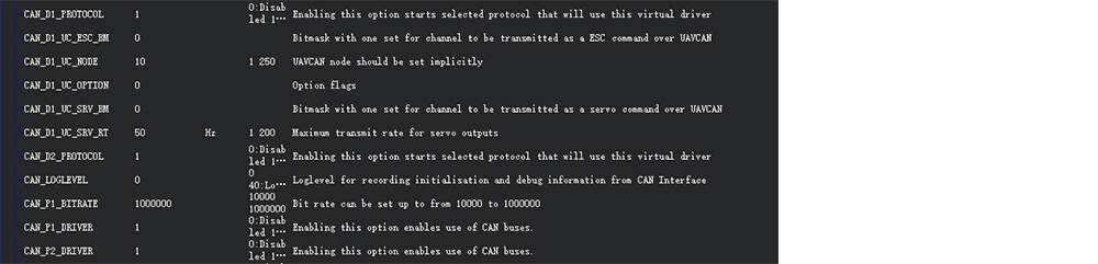
CAN_D1_PROTOCOL=1CAN_P1_DRIVER=1(Enable CAN1)CAN_D2_PROTOCOL=1**CAN_P2_DRIVER=1**(Enable CAN1)GPS_TYPE=9 OrGPS1_TYPE= 9(AP4.6.0 and later versions)
Set the flight control camera shutter output
* `CAM_TRIGG_TYPE`=1(0=PWM,1=ralay) * `CAM_RELAY_ON`=0(0=low,1=high) * `CAM_MIN_INTERVAL`=0(The shortest shutter interval time, unit: milliseconds, 1000=1 second) * `CAM_MAX_ROLL`=0(If the tilt exceeds this angle, the time-lapse shooting will not trigger until the angle returns to normal, 0=no limit) * `CAM_AUTO_ONLY`=0(When to on the shutter, 0=anytime, 1=only in AUTO mode) * `Relay_pin`=55(Ralay pin;The flight controller without io should be set to 63)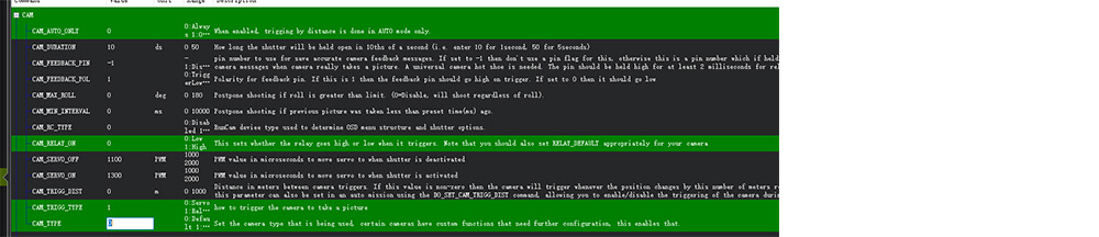
For AP4.6 and above version firmware
CAM1_TYPE=1(1=PWM,2=ralay)<br/> CAM1_RELAY_ON=0(0=low,1=high)<br/> CAM1_MIN_INTERVAL=0(The shortest shutter interval time, unit: milliseconds, 1000=1 second)<br/> CAM1_MAX_ROLL=0(If the tilt exceeds this angle, the delayed shooting will not be triggered until the angle returns to normal, 0=no limit) CAM_AUTO_ONLY=0 (when the shutter can be triggered, 0=any time, 1=only in AUTO mode<br/> Relay_pin=55(Ralay pin;The flight controller without io should be set to 63)<br/> CAM1_FEEDBAK_PIN=54(Ralay pin;The flight controller without io should be set to 62)<br/> CAM1_FEEDBAK_POL=1(0=low,1=high)<br/>Test shutter trigger
- Use the remote control to control the shutter:
RC?_OPTION=9(?=?=Remote control channel, for example, RC7_OPTION=9, then the remote control channel 7 is dialed to the high position to take pictures). - Ground station instructions:
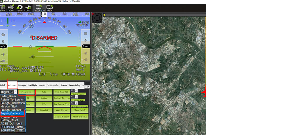
In the action bar of the flight data of the ground station, select Trigger_camera and click to execute the action to trigger the camera.
PX4
Note
The flight control parameters are set in QGroundcontrol》parameters. After modification, please click the ok button on the right and restart the flight control.
Enable UAVCAN
Note
The following settings are to enable UAVCAN to provide RTK/navigation data for the flight controller; if you only use C-RTK 2 as a PPK, you do not need to perform this operation.
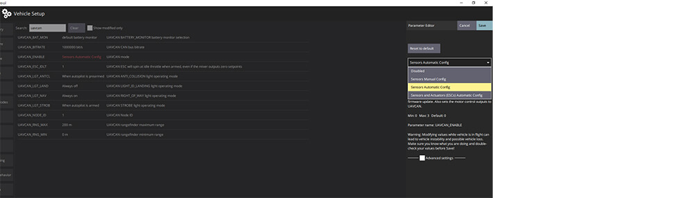
UAVCAN_ENABLE=Sensors Automatic Config(Automatic configuration of node iD)
Set the flight control camera shutter output
TRIG_MODE=1(Trigger mode)TRIG_INTERFACE=1 (relay)TRIG_PINS=?(Shutter trigger pin,If triggering on AUX5 and AUX6, it should be set to 56.)TRIG_ACT_TIME=200(Camera output duration, unit ms)TRIG_POLARITY=0(0=low,1=high)
C-RTK 2 parameters
Note
It is not necessary to configure C-RTK2 when using the relay to control the camera shutter; when the camera cannot be controlled to take pictures, please check the following parameters.
UAV_ENABLE=1(Enable shutter shutter input)UAV_MODE=0(Relay input mode)UAV_POLARITY=0(The trigger polarity of the shutter input; related to the flight control TRIG_POLARITY/CAM_RELAY_ON)CAM_DURATION=10(Duration that shutter is held open)CAM_POLARITY=0(Default:0)CAM_FEEDBACK_TYPE=1(Hotshoe is 1, shutter is 0)CAM_ST=0(Shutter compensation time, set to 0 when using the hotshoe)
PWM controlled shutter
This section describes the use of PWM to control the camera to take pictures and C-RTK2 to record POS data; the general camera is a relay to trigger the shutter.
ArduPilot firmware
Note
The flight control parameters are set in MissionPlanner >”Configuration”> All Parameter Table/Parameter Book. After modification, please click the write button on the right and restart the flight control.
Enable UAVCAN
Note
The following settings are to enable UAVCAN and provide RTK/navigation data for the flight controller; if you only use C-RTK 2 as PPK, this operation is not required.
- CAN_D1_PROTOCOL =1
- CAN_P1_DRIVER =1(Enable CAN1)
- CAN_D2_PROTOCOL =1
- CAN_P2_DRIVER =1(Enable CAN2)
- GPS_TYPE =9 or GPS_TYPE2= 9(Enable CAN GPS)
Set the flight control camera shutter
- CAM_TRIGG_TYPE=0(0=PWM ,1=relay)
- CAM_DURATION=10(uration that shutter is held open,0~50(1=100ms))
- CAM_SERVO_ON=1900
- CAM_SERVO_OFF=1100
- CAM_AUTO_ONLY=1
- Servo14_Function=10(Define the shutter trigger pin, take the flight control AUX6/M14/A14 pin as an example)
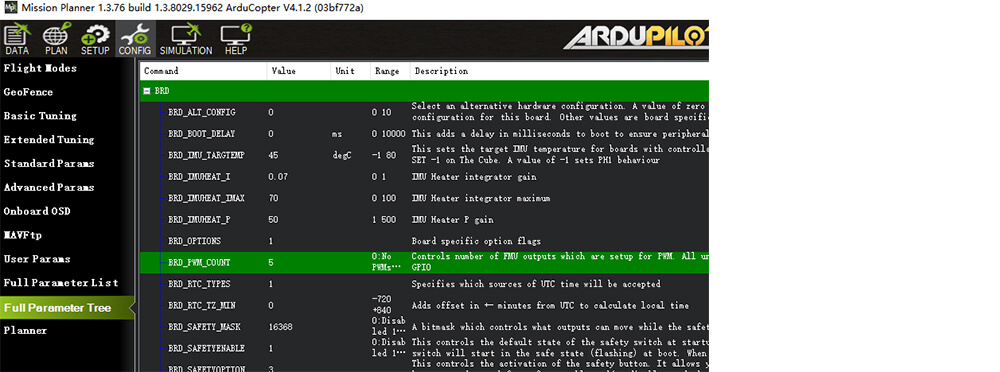
- BRD_PWM_COUNT=6(Take the V5+ A6 pin as an example, the firmware version below AP4.10 does not need to be set to a higher version; it should be equal to or greater than the PIN)
C-RTK 2 Parameters
When using PWM triggering, you need to modify the following parameters of C-RTK2:
- UAV_ENABLE=1(Enable camera shutter input)
- UAV_MODE=1(PWM input mode)
- UAV_DURATION=CAM_DURATION(flight control parameters)
- UAV_SERVO_ON=CAM_SERVO_ON(flight control parameters)
- UAV_SERVO_RATE=SERVO_RATE(flight control parameters)
- CAM_DURATION=10(Shutter ON time)
- CAM_POLARITY=0(0:low,1:high)
- CAM_FEEDBACK_TYPE=1(1 when the hot shoe triggers to record pos, and 0 when the shutter records pos)
- CAM_ST=0(Shutter compensation time, set to 0 when using hot shoe)
Test shutter trigger
- Trigger with remote control:
RC?_OPTION=9(?= Remote control shutter trigger channel, such as RC7_OPTION=9, then the remote control channel 7 is set to high to take a photo, the range is RC6~RC12). - Triggered with a ground station:
- Missionplanner>Data>Actions, select Trigger_camera, click to execute the action to trigger the camera to take a picture.
PX4 firmware
Note
The flight control parameters are set in the parameters of QGroundcontrol. After modification, please click the ok button on the right and restart the flight control.
Enable UAVCAN
Note
The following settings are to enable UAVCAN and provide RTK/navigation data for the flight controller; if you only use C-RTK 2 as PPK, this operation is not required.
- UAVCAN_ENABLE=Sensors Automatic Config (automatically configure node ID)
Set the flight control shutter trigger
- TRIG_MODE=1
- TRIG_INTERFACE=4 (PWM)
- TRIG_PWM_SHOOT=1900
- TRIG_PWM_NEUTRAL=1500
- TRIG_PINS=?(trigger pin. If triggering on AUX5 and AUX6, the set value should be 56)
- TRIG_ACT_TIME=200(trigger time)
C-RTK 2 Parameters
When using PWM to control shutter triggering, you need to modify the following parameters of C-RTK2:
- UAV_ENABLE=1(Enable camera shutter input)
- UAV_MODE=1(PWM)
- UAV_DURATION=TRIG_ACT_TIME/100(flight control parameters)
- UAV_SERVO_ON=TRIG_PWM_SHOOT(flight control parameters)
- UAV_SERVO_RATE=PWM_AUX_RATE(flight control parameters)
- CAM_DURATION=10
- CAM_POLARITY=0
- CAM_FEEDBACK_TYPE=11 when the hot shoe triggers to record pos, and 0 when the shutter records pos.
- CAM_ST=0(Shutter compensation time, set to 0 when using hot shoe)
Set up aerial survey control points
This section mainly describes how to set up control points correctly.
Overview
Control Point(Ground control point): It is mainly used to correct the three-dimensional space position error caused by various factors; the position accuracy of the control point will affect the accuracy of the results.
Check point: Measurement points used to calculate errors in aerial survey results
Control Point(Ground control point)
Use control points to correct the target three-dimensional space error caused by various factors; if you use RTK or PPK and do not require high accuracy, you can not lay out control points; the more control points, the more accurate the output, the better the results.
Tip
C-RTK2 PPK can reduce the control points by more than 80%. For common aerial survey areas and accuracy requirements, it is only necessary to ensure that there are 1 to 2 control points per square kilometer. Control points are not required if position errors of 5cm and more are allowed. The final effect is subject to the actual situation.
How to lay out control points?
- Start the RTK measuring instrument and connect the CORS account
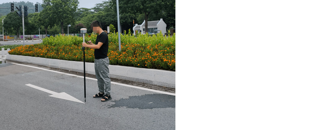
- Hold the RTK measuring instrument and make sure that the pole is perpendicular to the horizontal plane (the bubble of the spirit level is in the center)
- Enter the point measurement mode and wait to enter the fixed solution; when both HRMS and VRMS are greater than 0.02, click the point measurement icon to complete the measurement
- After the control point collection is completed, take at least 3 environmental photos of the control point.
- Create separate folders for control points, check points, and corresponding photos, and place them in separate folders; save the .csv files of all control points and checkpoints outside the folder
Tip
It is necessary to ensure the consistency of the image control points, check points and the result coordinate system.
Rules for laying control points
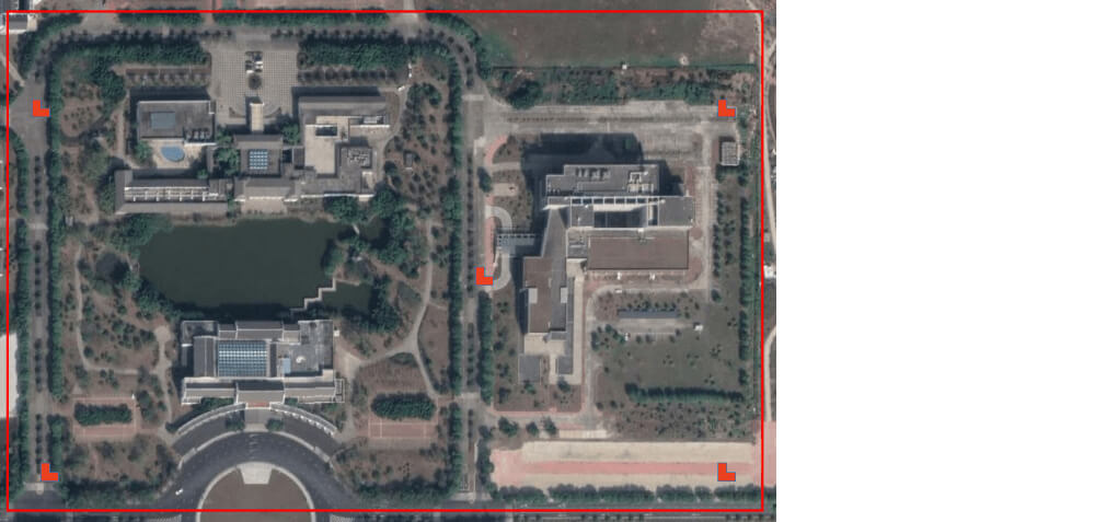
Regular rectangle
At least 4 control points (four corners) are arranged at the edge of the survey area in a small area, and one point is deployed in the middle area; control points are added in rules for a large area.
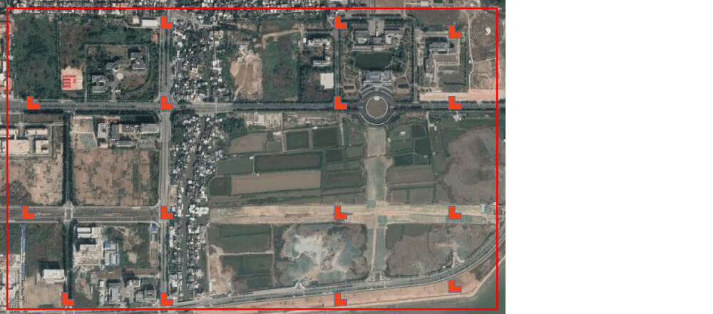
Irregular shape
In most cases, our aerial survey area is not regular. At this time, we need to comprehensively deploy the topography, convenience, and other factors of the points to be deployed, and try to ensure that the deployed control points can evenly cover the survey area.
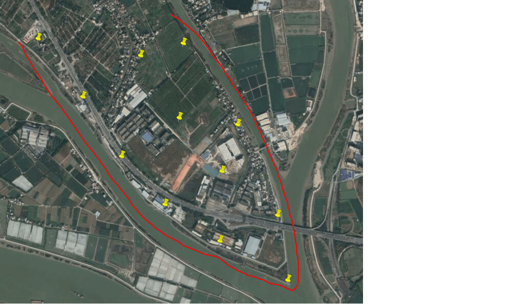
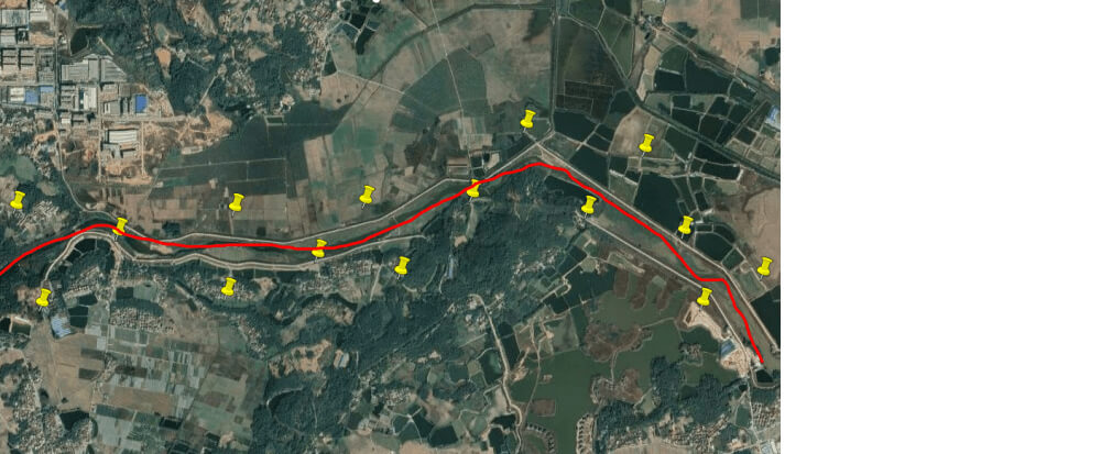
belt Aerial survey area
For banded areas such as rivers and highways, “Z” type control points are generally used.
Other situations that affect the layout of control points
- Camera pixel size: the higher the pixel size, the smaller the pixel density
- Flight altitude: The lower the flight altitude, the greater the density of control points.
- Equipment type: Aircraft with PPK (Post Differential System) have more than 80% fewer control points than those without PPK
Selection condition
- The general rule for selecting points is “Easy to find, easy to identify, good field of view, clear edges and corners.”
- The target of the control point should be flat, clear, without shadows, with good field of view conditions, which can be found from all angles, and it is not recommended to lay control points next to trees and buildings.
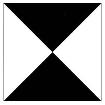
- Control points need to be selected as sharp markers with clear edges and corners
- Manual control point marking paint width>30CM, markers should be larger than 70CM
- The control point identification should be clearly different from the surrounding color
Control point sign
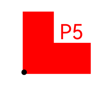
Make control point signs, use a right-angle mold to spray, or use a special sign for aerial survey; the sign is larger than 50cm, with a logo and a clear identification number, and the logo must be at a right angle; the height of the font is greater than 30cm.
Other control point signs
In the urban environment, if there is no condition to make a mark like the control point mark, the road indicating arrow can also be used as the control point sign.

Set up PPK base station
This section briefly describes how to quickly set up a PPK base station.
Note
Most professional RTK measuring instruments (RTK base stations) on the market can be used as PPK base stations (requires support for saving statically collected observation data).
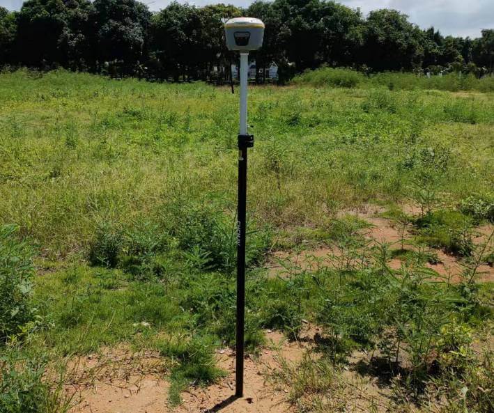
Set up the base station
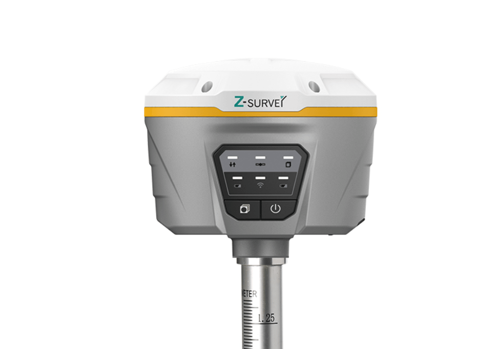
- The PPK reference station should choose a handheld RTK measuring instrument similar to the above figure; (recommended to choose a local manufacturer)
Note
The PPK base station needs to be purchased by yourself; please refer to the corresponding equipment tutorial for related tutorials.
Set up the base station
- Set up the base station in an open area, turn on the base station, and connect to CORS
- Enter the “point measurement” mode, and after entering the fixed solution, collect the position coordinates of the current point.
- Enter the static acquisition mode and keep the base station performing static acquisition during the flight of the aircraft.
- After the flight is over, end the static collection.
Tip
When you don’t have a PPK base station and don’t need a control point, you can choose to use NTRIP; instead of a PPK base station
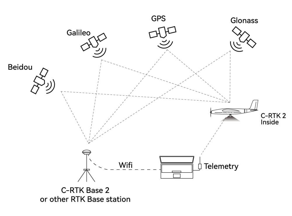
As both PPK and RTK
If you are acting as both PPK and RTK, it is recommended to use the CORS/NTRIP service as the base station; just use the data link to establish a ground station to communicate with the aircraft.
Aerial survey mission planning
Video
PPK data solution
This paper mainly describes how to convert the data format of the PPK mobile station and base station, and how to use RTKlib to solve PPK.
Video
Note
If the original data storage format of the base station is RINEX, there is no need for data format conversion, and it can be directly imported into RTKPOST software and C-RTK2 for differential calculation.
3D modeling software
- dji terra
- Pix4d
- Smart3d(ContextCapture)
Note
The above software is commercial software; please purchase genuine software.
Parameter meaning
Parameter file
The parameters of C-RTK2 are saved in the TF card directory. You only need to connect C-RTK to the computer, open the “c-rtk 2_config.conf” file with a text editor, make your changes, and save it; the changes will take effect after restarting the device.
Parameter
- SYS_MODE=1
- System mode. 0:Base, 1:Rover(default)
- SYS_UTC=0
- Time zone. default:8
- SYS_LOG=1
- System log enabled. 0:Disable(default), 1:Enable
- AHRS_ROTATION=4
- Rotation direction of accelerometer, gyroscope, and compass. (default:4, ROTATION_YAW_180)
- ROTATION_NONE = 0,
- ROTATION_YAW_45 = 1,
- ROTATION_YAW_90 = 2,
- ROTATION_YAW_135 = 3,
- ROTATION_YAW_180 = 4,
- ROTATION_YAW_225 = 5,
- ROTATION_YAW_270 = 6,
- ROTATION_YAW_315 = 7,
- ROTATION_ROLL_180 = 8,
- ROTATION_ROLL_180_YAW_45 = 9,
- ROTATION_ROLL_180_YAW_90 = 10,
- ROTATION_ROLL_180_YAW_135 = 11,
- ROTATION_PITCH_180 = 12,
- ROTATION_ROLL_180_YAW_225 = 13,
- ROTATION_ROLL_180_YAW_270 = 14,
- ROTATION_ROLL_180_YAW_315 = 15,
- ROTATION_ROLL_90 = 16,
- ROTATION_ROLL_90_YAW_45 = 17,
- ROTATION_ROLL_90_YAW_90 = 18,
- ROTATION_ROLL_90_YAW_135 = 19,
- ROTATION_ROLL_270 = 20,
- ROTATION_ROLL_270_YAW_45 = 21,
- ROTATION_ROLL_270_YAW_90 = 22,
- ROTATION_ROLL_270_YAW_135 = 23,
- ROTATION_PITCH_90 = 24,
- ROTATION_PITCH_270 = 25,
- ROTATION_PITCH_180_YAW_90 = 26,
- ROTATION_PITCH_180_YAW_270 = 27,
- ROTATION_ROLL_90_PITCH_90 = 28,
- ROTATION_ROLL_180_PITCH_90 = 29,
- ROTATION_ROLL_270_PITCH_90 = 30,
- ROTATION_ROLL_90_PITCH_180 = 31,
- ROTATION_ROLL_270_PITCH_180 = 32,
- ROTATION_ROLL_90_PITCH_270 = 33,
- ROTATION_ROLL_180_PITCH_270 = 34,
- ROTATION_ROLL_270_PITCH_270 = 35,
- ROTATION_ROLL_90_PITCH_180_YAW_90 = 36,
- ROTATION_ROLL_90_YAW_270 = 37,
- ROTATION_ROLL_90_PITCH_68_YAW_293 = 38,
- ROTATION_PITCH_315 = 39,
- ROTATION_ROLL_90_PITCH_315 = 40,
- ROTATION_PITCH_7 = 41,
- Rotation direction of accelerometer, gyroscope, and compass. (default:4, ROTATION_YAW_180)
- GPS_UPDATE=0
- Perform a GPS firmware update after restarting. 0:Disable(default), 1:Enable
- GPS_RATES=5
- GPS Refresh rate. range:1~20(1=1Hz)
- GPS_GNSS=0
- GNSS system configuration. 0:GPS+GLO+GAL+BDS(default), 1:GPS+GLO+GAL, 2:GPS+GAL, 3:GPS+GLO, 4:GPS+BDS
- GPS_BASE_MODE=1
- Base Receiver mode. 1:Survey-in(default), 2:Fixed Mode
- GPS_BASE_MIN_DUR=60
- Survey-in mode convergence time. range:0~86400(1=1s)
- GPS_BASE_ACC_LIMIT=2.500000
- Survey-in mode convergence accuracy. range:0~9999(1=1m), default:2.5
- UAV_ENABLE=1
- Shutter input enable. 0:Disable, 1:Enable(default)
- UAV_MODE=0
- Shutter input mode. 0:Relay(default), 1:PWM
- UAV_POLARITY=0
- Whether the shutter is open is high or low. 0:Low(default), 1:High
- UAV_SERVO_ON=1300
- PWM value in microseconds to move the servo when the shutter is activated. range:1000~20000(1=1us), default:1300
- Servo rate. range:25~400(1=1Hz), default:50
- UAV_SERVO_RATE=50
- Servo rate. range:25~400(1=1Hz), default:50
- CAM_FEEDBACK_TYPE=1
- Camera feedback type. 0:None, 1:Hot Shoe(default)
- CAM_FEEDBACK_DURATION=0
- Camera feedback signal duration. range:0~100(1=1ms), default:0
- CAM_FEEDBACK_INVERTAL=1
- Camera feedback interval. range:0~30000(1=1ms), default:1
- CAM_DURATION=10
- The duration that the shutter is held open. range:0~50(1=100ms), default:10
- CAM_POLARITY=0
- Whether the shutter is open is high or low. 0:Low(default), 1:High
- CAM_ST=0
- Shutter time compensation. range:-99999~99999(1=1ms), default:0
- USB_TYPE=3
- USB type. 0:Close, 1:Debug, 3:RTCM(default), 5:GPS
- SERIAL1_TYPE=1
- USB type. 0:Close, 1:Debug, 3:RTCM(default), 5:GPS
- SERIAL1_BAUD=115200
- USB type. 0:Close, 1:Debug, 3:RTCM(default), 5:GPS
- BOARD_BARO_ENABLE=0
- Barometer enable. 0:Disable(default), 1:Enable
- BOARD_COMPASS_ENABLE=1
- Compass enable. 0:Disable, 1:Enable(default)
Upgrade firmware
This section mainly describes how to quickly upgrade the C-RTK 2 system and F9P receiver firmware.
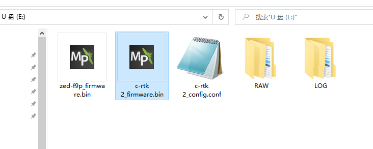
C-RTK 2 Firmware
- Name the firmware as“c-rtk 2_firmware.bin”
- Connect C-RTK2 to the computer, find the storage disk corresponding to C-RTK (the drive letter is U disk)
- Put the “c-rtk 2_firmware.bin” file in the root directory of the SD card, restart C-RTK2, and the system will automatically update the firmware after startup.

Upgrading F9P Receiver Firmware
- Download the firmware file
- Name the file “zed-f9p_firmware.bin”
- Connect C-RTK2 to the computer, find the storage disk corresponding to C-RTK (the drive letter is U disk)
- Place the “zed-f9p_firmware.bin” file in the SD root directory.
- Open the “c-rtk 2_config.conf” file and modify the parameter GPS_UPDATE=1.
- Reboot to C-RTK 2; the RUN yellow status light flashes (100ms on and 100ms off) to update the F9P receiver firmware; just wait for the update to complete.
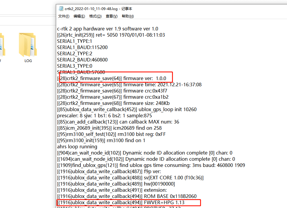
Check firmware version
C-RTK 2 records the relevant operation information of C-RTK2 in the log file, such as C-RTK 2 and F9P firmware version.
Why PPK is ideal for aerial surveys
This section mainly describes why aerial surveys prefer PPK over RTK/GPS.
Why is GPS not suitable for aerial surveys?
- Low work efficiency
- If the aerial survey adopts ordinary GPS positioning, to correct the error, it is necessary to send people to set up a lot of control points on the spot, but using RTK/PPK can eliminate or only need very few control points; and most surveying and mapping areas have complex geographical environments, and it is difficult for outdoor staff to Set up enough control points; and when processing data, it takes a lot of time to mark and search for a large number of control points.
- Poor result, positioning accuracy
- GPS positioning accuracy is far from RTK and PPK. If GPS positioning is used, it is difficult to meet the accuracy requirements for aerial survey results, and even forming the results is difficult.
Tips RTK/PPK can reduce control points by more than 80% and can achieve centimeter-level positioning.
- GPS positioning accuracy is far from RTK and PPK. If GPS positioning is used, it is difficult to meet the accuracy requirements for aerial survey results, and even forming the results is difficult.
Why is GPS not suitable for aerial surveys?
RTK (Real-Time Kinematic): real-time dynamic carrier phase technology is a technology in which the base station sends the positioning error to the mobile station through the data link, and the mobile station corrects the positioning through the error information to obtain centimeter-level positioning.
PPK (post-processed kinematic): Post-process carrier phase differential positioning technology, which is a simultaneous observation of the base station and the mobile station to form a virtual carrier phase observation, determine the relative position between the receivers, and finally introduce the base station. The known coordinates of the rover to obtain the three-dimensional coordinates of the rover
**The difference between RTK and PPK:
Communication method is different: RTK requires radio or network to transmit positioning error data in real time, while PPK technology mobile station and base station do not need real-time communication.

Different working methods: RTK uses real-time kinematic, which can view the currently processed coordinates in real time; PPK needs a PPK solution to obtain accurate positioning information of the target point.
- Different working radius: RTK is restricted by the communication station, and the baseline distance is less than 10km. Even if the mobile network is adopted, it is difficult to ensure an uninterrupted network; PPK technology operation does not require real-time communication. Generally, the operation radius can reach 50km.
- Affected by the environment, during RTK operation, it is very easy to lose the lock when passing obstacles such as trees, houses, and mountains, and it is not easy to lose the lock during PPK operation.
- Different positioning accuracy: RTK participates in the calculation of real-time epoch data, while PPK can solve a cycle of epoch data through post-difference, which can not only improve the probability of fixed solutions but also have high solution accuracy, which can generally reach the millimeter level.
Advantages of PPK
- The base station and the mobile station do not need real-time communication
- Large working radius (long baseline distance): up to 60km or more
- It is suitable for the complex environment of aerial survey, and the environment has a low impact on it.
- High positioning accuracy
- Reduce control points by more than 80%, or even eliminate control points.
Procurement/Purchasing Communication
Laura
E-mail:Laura@cuav.net
WhatsApp:(+86)18078814327
Tina
E-mail:Tina@cuav.net
WhatsApp:(+86)18122367332
