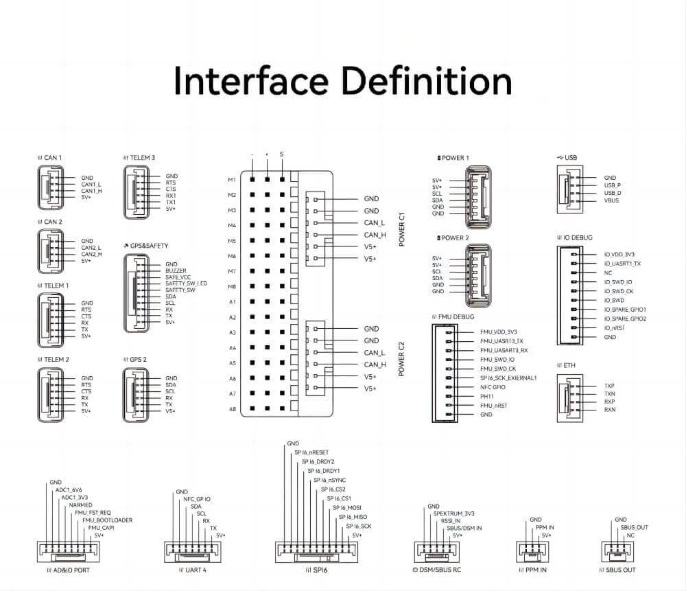
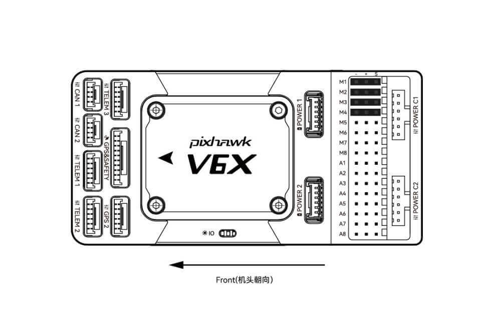
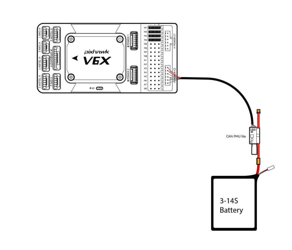
| POWER C1 | Please connect CAN PMU SE to this interface; this interface is connected to the UAVCAN power module |
| POWER C2 | Please connect CAN PMU SE to this interface; this interface is connected to the UAVCAN power module. |
| POWER 1 | Connect SMbus(I2C) power module |
| POWER 2 | Connect SMbus(I2C) power module |
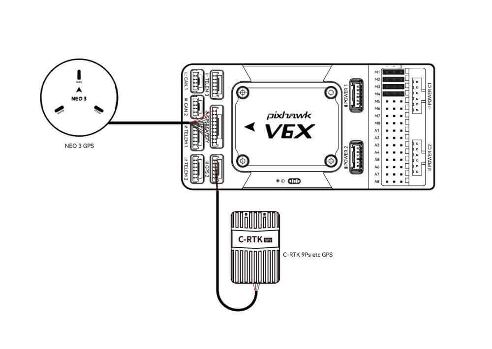
| GPS&SAFETY | Connect Neo series GPS/C-RTK 9PS, including GPS, safety switch, buzzer interface. |
| GPS2 | Connect the GPS/RTK module |
| UART 4 | Support user customization |
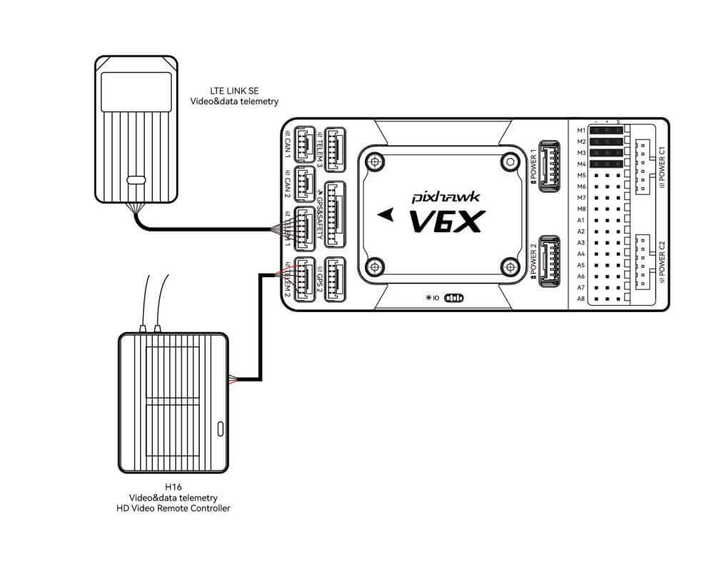
| TELEM1/TELME2/TELEM3 | Connect telemetry or MAVLink devices |
| TF CARD | SD card for log storage (card pre-inserted in factory). |
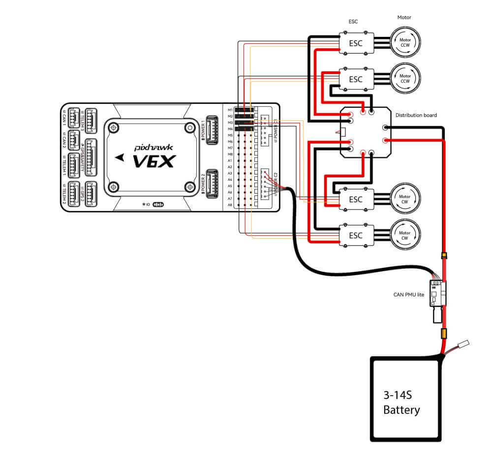
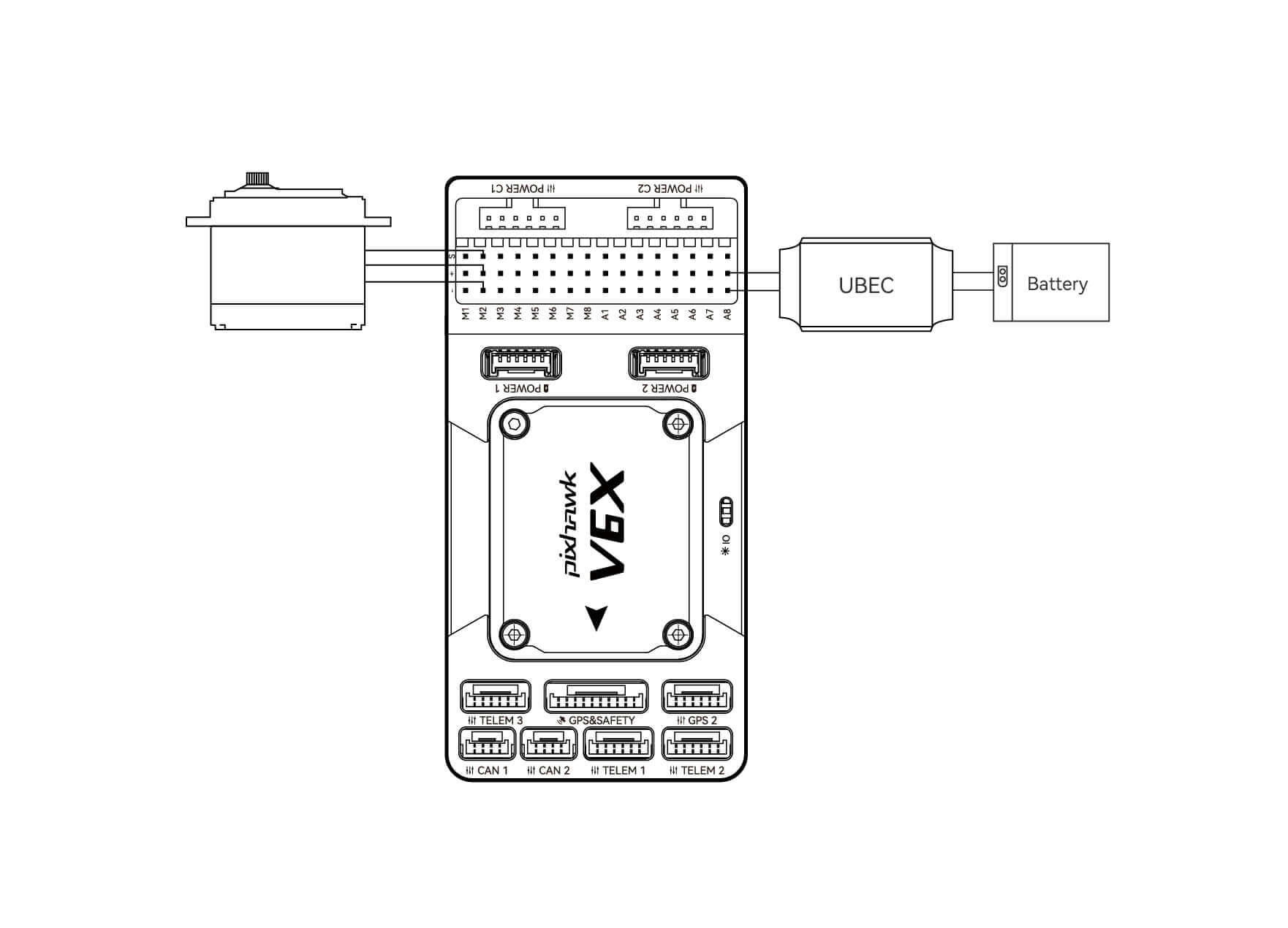
| M1~M8 | PWM output from IO, connecting to ESC and Servo |
| A1~A8 | Form FMU can be defined as PWM/GPIO; supports Bdshot; used to connect camera shutter/hot shoe, servo, etc. |
| USB | Connect to a computer for communication between the flight controller and the computer, such as loading firmware. |
| CAN1/CAN2 | Connect Dronecan/UAVCAN devices such as NEO3 Pro. |
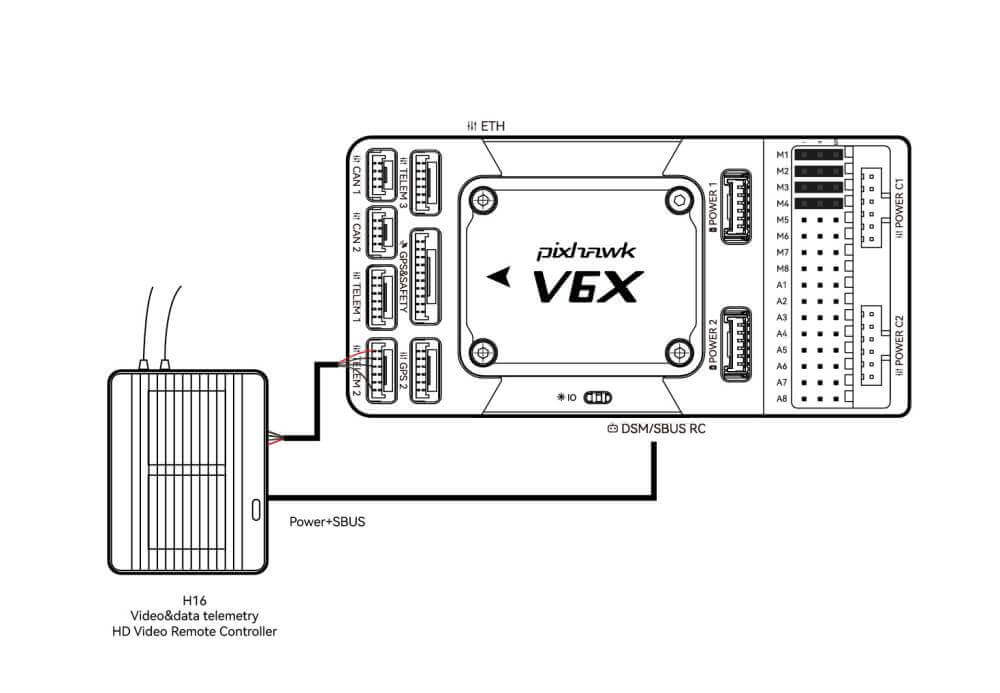
| DSM/SUB/RSSI | Includes DSM, SBUS, RSSI signal input interface, DSM interface can be connected to DSM satellite receiver, SBUS interface to SBUS remote control receiver, RSSI for signal strength return module |
| PPM | Connecting the PPM RC Receiver |
| ETH | Ethernet interface, you can connect Ethernet devices such as task computers. |
| AD&IO | There are two analog inputs (ADC3.3/ADC6.6); generally not used |