APM: Copter supports two main types of aircraft—multirotors and helicopters; this section focuses primarily on the installation and use of multirotors.
Multi-rotor aircraft
Brushless motors and electronic speed controllers provide lift and directional control, delivering varying levels of thrust.
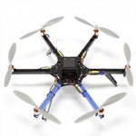
The design is simple and safe, with configurations ranging from three to eight rotors—the quadcopter (four-rotor) being the most common.
These aircraft offer excellent load-carrying capabilities and remain operational even in strong winds.
Surplus lift capacity enhances the overall safety margin.
Various factors allow for flexible options to increase payload capacity conveniently.
Helicopter
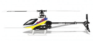
Common helicopter configurations include single-rotor, tandem-rotor, transverse-rotor, and coaxial-rotor types.
The helicopter type most commonly used for drones is the single-rotor configuration; currently, flybarless models are particularly popular.
Directional control is maintained by using servos to drive a linkage mechanism that alters the rotor blade pitch (many versions of these aircraft exist—covering them all is beyond the scope of this manual, as this type of mechanical system requires specialized study and independent technical support).
Powerful, fast, and efficient—a highly capable performer suitable for a wide range of missions.
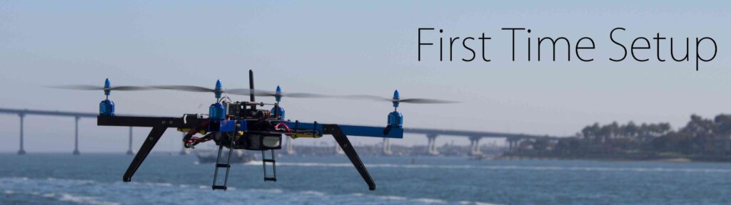
First Time Setup
The initial setup of the autopilot involves downloading and installing the Ground Control Station (GCS), mounting the autopilot to the airframe, connecting the remote control receiver, power supply, and ESCs/motors, and then performing the initial configuration and calibration.
This section assumes that you have already selected the frame and the autopilot.
System composition of a multi-rotor UAV
Multi-rotor type
The multi-rotor configurations currently supported by ArduPilot include: dual-rotor, tricopter, quadcopter, hexacopter, octocopter, Y6, X8 (quad-frame with eight propellers), and Hexa-12 (hex-frame with twelve propellers). The following uses the simplest configuration—the quadcopter—as an example.
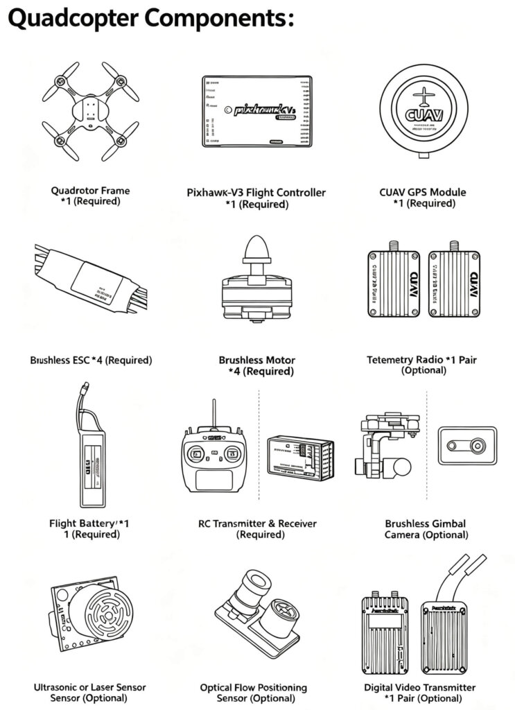
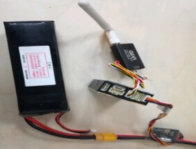
Wireless data telemetry system (Xbee/P900/Xtend/ltelink) x1 pair (Required)
Flight battery (Required)
RC transmitter and receiver (Required)
Brushless gimbal or camera (Optional)
Ultrasonic or laser sensor (Optional)
Optical flow sensor for position holding (Optional)
Supported battery types:
Typically, the power module supplied with the flight controller is used: the CUAV low-voltage PM module supports standard 3–6S flight batteries; the HV PM module supports 3–12S batteries; and the CAN PMU module supports 2–14S batteries.
How high and how far can it fly:
Flight altitude and range depend on your drone’s power and battery life. Please note that you must fly in compliance with local laws and regulations; otherwise, you will be solely responsible for any legal consequences.
Theoretically:
Real-time control of flight altitude and range depends on the propulsion system, flight endurance, and the communication range of the remote controller or data link.
Autonomous flight altitude and range depend on the propulsion system and flight endurance. A multi-rotor system typically comprises the following hardware components (using a quadcopter as an example):
Introduction to and Use of the Ground Station
ArduPilot is compatible with a wide range of ground control stations (GCS).
Developers typically use Windows-based GCS software, as these often offer more in-depth capabilities for parameter configuration and advanced debugging. If your primary goal is simply to fly, you might opt for a GCS that runs on mobile operating systems like iOS or Android.
Below are links to install some popular GCS systems:
Mission Planner (MP) is a dedicated ground control station for APM and Pixhawk systems running on Windows. It is also a fully open-source ground control station.
Its key functions include:
Flashing firmware to APM/Pixhawk units
Installing, configuring, and optimizing parameters
Planning waypoint missions using Google Maps or other map services
Downloading and analyzing flight logs
Conducting hardware-in-the-loop (HITL) simulations via a dedicated PC flight simulation interface
Connecting a telemetry radio, which also allows you to: Monitor aircraft status in real-time Record real-time telemetry logs View and analyze telemetry logs Operate the drone via FPV (First-Person View)
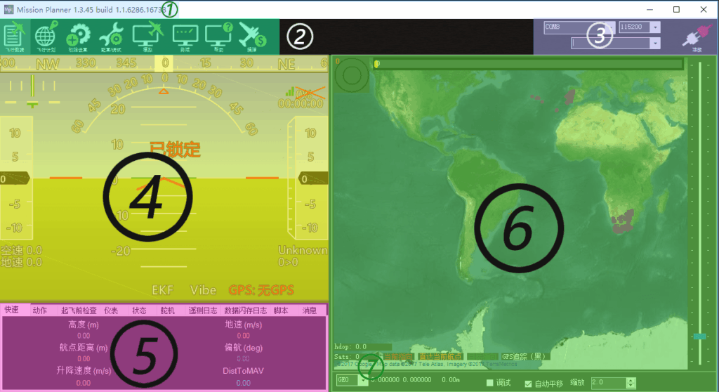
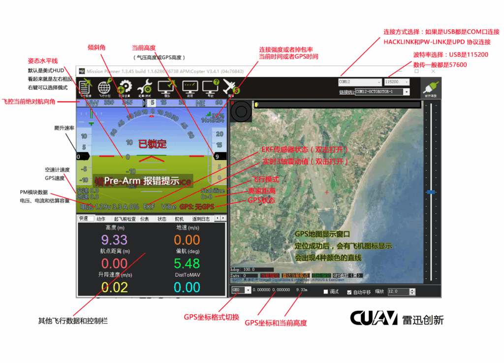
Introduction to Main Window Functions: (For detailed functions, please refer to the sub-sections)
Software version number; the flight controller’s software version is also displayed upon connection.
Main function options area.
Connection method selection and connect/disconnect controls.
Aircraft dashboard, including attitude, altitude, GPS status, and flight mode.
Status and auxiliary control functions area.
GPS map; displays real-time location and flight path once the flight controller and GPS are connected.
GPS coordinates and accuracy display.
Install Mission Planner Ground Station
Both Mission Planner and QGroundControl ground stations support ArduPilot firmware, but Mission Planner may offer better compatibility with newer ArduPilot firmware versions.
The following section primarily describes the installation of Mission Planner.
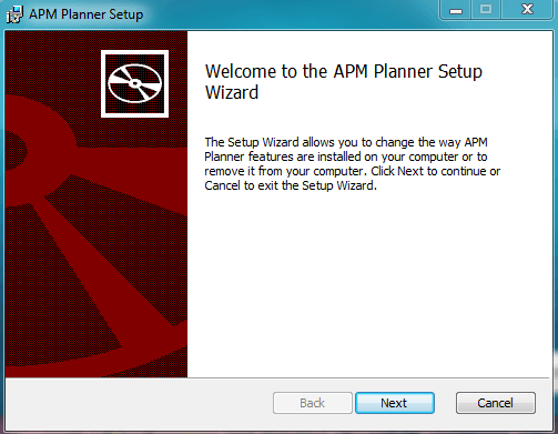
Open the installer file, then double-click to run the installer.
The drivers are installed automatically when you set up the ground station. (Windows 10 includes built-in drivers and recognizes the unit as a standard Microsoft device, allowing for normal operation.) However, in China, driver installation often fails—triggering a “system cannot find the specified file” error—due to the prevalence of “Ghost” clone systems (which are often stripped-down or incomplete versions of Windows). To resolve this, we recommend reinstalling Windows 10 to ensure better compatibility.
Simply keep clicking “Next” and proceed with the default installation.
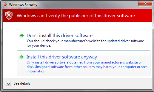
If prompted to install the driver, select “Install this driver software anyway.”
Mission Planner is typically installed in the `C:\Program Files (x86)\APM Planner`
or the `C:\Program Files\APM Planner` folder. Your log file folder will also be located within this installation directory.
Update Mission Planner
Mission Planner automatically checks for new versions upon startup (when connected to the Internet).
To ensure compatibility between the ground station and the firmware, please always run the latest version of Mission Planner.
Connect to the flight controller using Mission Planner.
Overview
This section primarily introduces the connection methods for the MP ground station.
Supported connection methods:
Mission Planner supports the following connection methods:
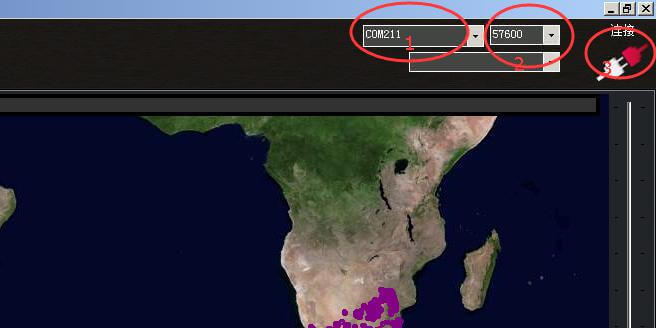
Direct USB connection to the flight controller (for parameter configuration and firmware flashing): In the Ground Station, select the flight controller’s COM port and set the baud rate to 115200 (default).
Telemetry connection: Standard telemetry modules also connect via USB, as the ground-side unit typically has a built-in USB-to-serial chip; in the Ground Station, select the specific port number, and the baud rate is generally 57600.
3. TCP connection method; used by some network-based TCP-to-serial devices; CUAV currently does not offer TCP-to-serial devices.
4. UDP connection method; PW-LINK and WtrLINK utilize this communication method.
Flight Data: Introduction and Usage
Overview
The “Flight Data” screen is the default main interface of the MP Ground Station. It provides an intuitive overview of your drone’s status, including attitude, speed, altitude, distance from the home point, GPS location data, and more.
It is divided into three main functional areas:
Flight HUD window (top-left)
Status display and control options panel (bottom-left)
Map and real-time aircraft location information (right)
The functions of each area are detailed below.
Main Interface Overview
Introduction to the Status Display and Flight Control Bar
Quick Display Bar
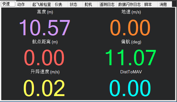
Primarily displays six parameters:
Current altitude and ground speed,
Distance to waypoint,
Course deviation angle (heading),
Vertical speed,
DistToMav (distance from the drone to the home point), etc.
You can right-click in the display area to configure which rows or columns are shown, and double-click a specific display field to set its content.
Motion control
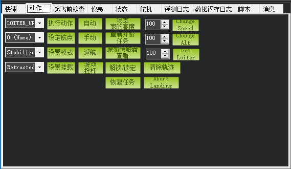
This function bar allows for real-time operations such as mode switching, mission control, and altitude/speed adjustments. Automatic Flight Path Mission: Configure the action checkboxes to “Mission Start” > “Arm/Disarm” > “Auto/Execute Action” (note that the first mission step must be set to “Takeoff”). Raw Sensor Data: View raw sensor data for performance monitoring or fault analysis.
Game Controller: Map a USB gamepad to a remote control channel to pilot the aircraft (use is not recommended, as packet loss over standard data links may result in unresponsive or jerky control).
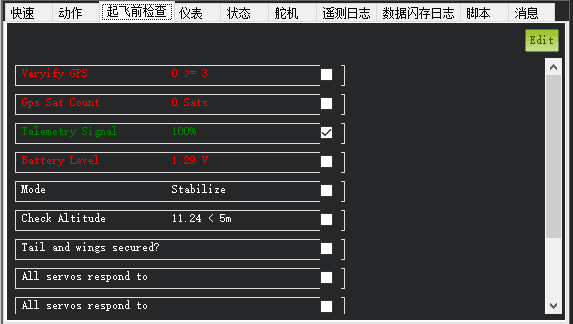
Pre-takeoff check
It helps beginners check and determine whether the aircraft meets the conditions for flight—for example, by providing alerts regarding the number of GPS satellites and battery voltage. Indicators turn red if conditions are not met and green if they are. Users can also utilize the “EDIT” button to customize alert options and thresholds.
As ArduPilot firmware becomes increasingly sophisticated, the flight controller performs its own local self-check; if the check fails, the system cannot be armed, so this specific function area can be ignored.
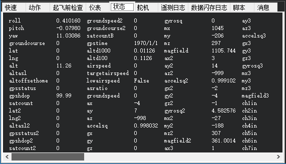
Status bar
This area displays all flight controller data, including sensor readings, channel input/output data, and more. This section can be used for both flight operations and debugging.
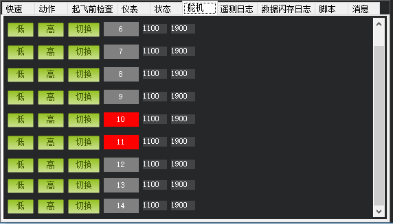
Servo - Channel Control
Servo—despite the name, it is not limited to controlling steering mechanisms; it can also control other devices, such as camera shutters. In practice, it functions as a PWM output control channel.
For multi-rotors, if a specific function has been assigned to a channel, you will not be able to control that channel from here.
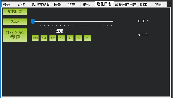
Telemetry logs
Used for loading and playing back telemetry logs recorded by the ground station.
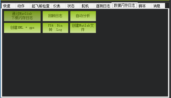
Data Flash Log
Download Flash Logs via MAVLink: Flight logs recorded on the onboard SD card can be downloaded via USB (if the log file is very large, it is recommended to remove the SD card directly to read the data). Review Logs: Flash logs can be opened for detailed analysis. Automated Analysis: Use the program’s automated analysis function to process flash logs and generate immediate results, allowing for a clear assessment of whether data—such as vibration levels and compass readings—falls within acceptable limits.
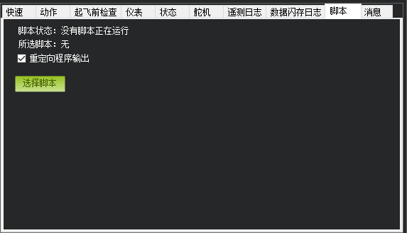
Script
Load control script
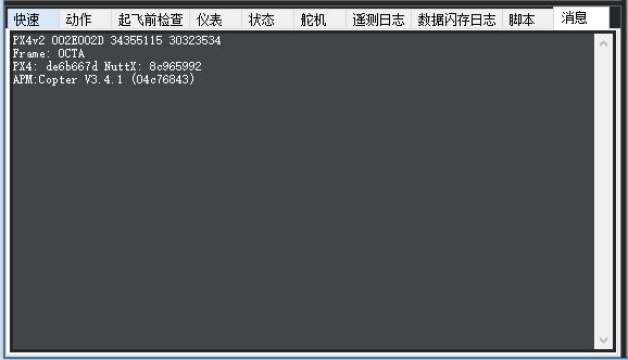
Information
Displays the Pre-Arm information, firmware version, and hardware type sent by the aircraft.
Flight Planning / Mission Planning
Overview
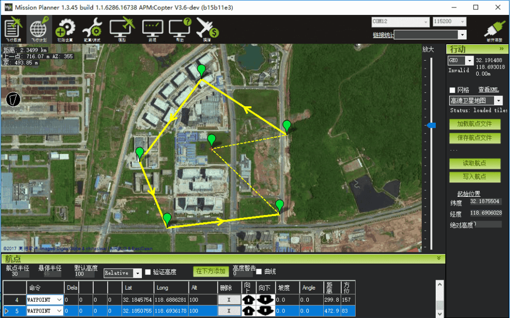
Flight planning is one of the most important features in Mission Planner (MP). General users can employ it to plan straightforward flight missions—including altitude control for each waypoint, loiter times, camera triggers, various conditional or channel-based triggers, and even automated takeoff and landing sequences.
Industry professionals can also use it for tasks such as mapping and surveying mission planning.
This section focuses on the mission planning functionality of the MP ground station, though the underlying concepts of waypoint planning are actually very similar across other ground stations.
Examples of automated tasks
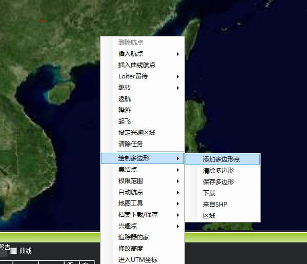
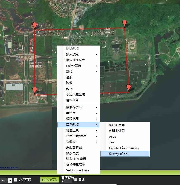
Create a multi-waypoint area in the Mission Planner mission planning interface.
Within the area, right-click to open the menu and select Auto Waypoint > Survey (Grid).
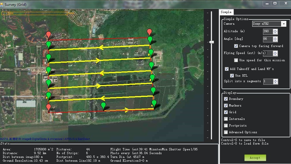
Mission Planner will display the configuration interface, which defines camera parameters and automatically calculates the photo-taking distance—specifically, the parameter for the DO_SET_CAM_TRIGG_DIST command; you can also adjust these parameters based on actual conditions.
If you accept these parameters, click “Accept”; Mission Planner will generate a series of waypoints covering the specified area, including takeoff and landing points. The `DO_SET_CAM_TRIGG_DIST` command is used to set the trigger distance for the camera shutter; finally, call `DO_SET_CAM_TRIGG_DIST` again to reset the parameter to 0 and stop taking photos. Note that the parameters used in the two calls differ.
Initial Setup
This section is accessed via the “Initial Setup” menu in Mission Planner; it is an essential interface for configuring your flight controller. The interface is divided into the following sections: Install Firmware, Wizard, Mandatory Hardware, and Optional Hardware.
Install firmware
If you wish to update the program (firmware) running on the flight controller, you must upload the new firmware to the flight controller.
Required hardware
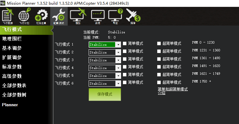
You will see this menu item if the autopilot is connected. Click it to view the required setup tasks before operating the aircraft. Essential settings for every drone include frame type, accelerometer calibration, compass calibration (onboard calibration can be triggered via the remote controller), remote controller calibration, ESC calibration (which can be performed offline), flight modes, and failsafe settings.
Basic setup for the drone is now essentially complete, covering frame type configuration, accelerometer calibration, compass calibration (onboard calibration can be triggered via the remote controller), remote controller calibration, ESC calibration (supports offline calibration), flight modes, and failsafe settings.
Optional hardware
Before operating the aircraft, click this menu item to review the tasks you may need to complete—primarily setting up, enabling, and disabling optional hardware.
For more information, please visit the Optional Hardware section.
Mission Planner Configuration/Debugging Interface
The configuration/tuning interface is where you set the parameters that determine how your autopilot controls your aircraft. Tuning involves adjusting parameters within the control loops so that your aircraft behaves as expected. While most of these parameters come with default values, some must be configured before the first flight. Selecting a menu item opens a new interface displaying more detailed parameters.
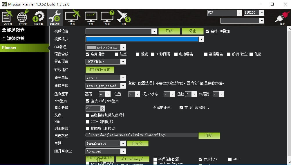
Planner
This is where you configure most of the settings for how Mission Planner operates. Options include video device, video format, OSD color, telemetry log storage location, and your preferred units of measurement.
Airplane mode
You will see this menu item if the autopilot is connected (Mission Planner version 1.3.50 or later).
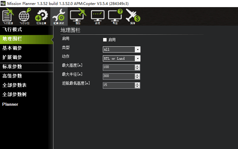
Geofencing
You will see this menu item if the autopilot is connected. You can configure your geofence on this screen.
Basic hyperparameter tuning
Please look out for the details in the upcoming explanatory article on “First Flight.”
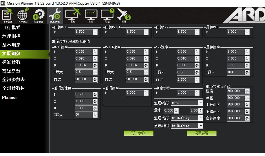
Extended hyperparameter tuning
You can adjust your drone’s PID settings here to make its flight more stable.
Standard parameters
You will see this menu item if the autopilot is connected. You can configure certain key parameters.
Advanced parameters
You will see this menu item if the autopilot is connected. You can configure certain advanced parameters in this interface.
Complete parameter list (tree)
If the autopilot is connected, you will see these two menu items. These items provide the interface for tuning all flight control parameters.
CUAV Hflight
Overview
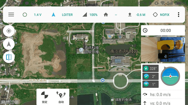
CUAV Hflight is an Android-based ground control station developed by CUAV as an optimized version of Tower.
It supports USB, Bluetooth, and Wi-Fi connections and is compatible with the entire CUAV family of data link products, including:
ONE BOX: Bluetooth data link
HACKLINK: HD digital data link
PW-LINK: Wi-Fi data link
CUAV RADIO: SiK point-to-point data link (available in 433MHz or 915MHz bands; power options: 100mW, 250mW, 500mW)
CUAV XB RADIO: 250mW point-to-point data link with an integrated, imported Digi S3B module
CUAV XTEND RADIO: 1W point-to-point data link with an integrated Digi Xtend 1W module
The above covers the tutorial on the initial setup and ground station usage for multi-rotor aircraft. Please stay tuned for the next installment: 《Initial Setup of a Multi-Rotor Aircraft -Ⅱ (Aircraft Assembly)》