
Advanced Settings for Multi-rotor Aircraft
Auto-tuning is a feature available in ArduCopter firmware version 3.2 and later. It automatically adjusts the Stabilize P, Rate P, and Rate D parameters, resulting in improved agility and stability without significant overshoot. You must switch to Altitude Hold mode before initiating the auto-tuning process.
Setup Procedure
1. Configure a flight mode as “Altitude Hold” (AltHold).
2. Assign Channel 7 or Channel 8 as the switch for AutoTune; for example, set Channel 7 to “AutoTune,” as shown in the image.
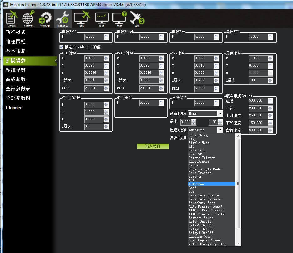
3. Ensure that channel 7 or 8 is set to the low position before takeoff.
4. Conduct the test flight in a clear, open area.
5. After takeoff, switch to Altitude Hold mode once the aircraft is in a suitable position.
6. Toggle channel 7 or 8 to the high position to initiate Auto-Tune.
7. Once Auto-Tune is complete, the aircraft will revert to its original PID settings.
8. To test the PID values generated by Auto-Tune, toggle channel 7 or 8 from the low position to the high position; the aircraft will then use the tuned PID values.
9. To continue using the original PID settings, simply set the switch to the low position.
10. If you wish to save the tuned PID values, keep channel 7 or 8 in the high position before disarming the aircraft. If you do not wish to save them, set the switch to the low position before disarming.
Note: The effectiveness of Auto-Tune depends on factors such as the airframe; in some cases, it may lead to a crash.
Accessibility toggle
This section demonstrates how to set up function switches that are triggered via auxiliary functions on your transmitter. In AC3.2.1 and earlier versions, channels 7 and 8 could be used as auxiliary switches. This applies to firmware version AC3.3 and later.
Configuration
By default, auxiliary switches are disabled. You can enable them via the “Extended Tuning” options in the configuration/tuning section, or by directly configuring the `CH7_OPT`, `CH8_OPT`, `CH9_OPT`, `CH10_OPT`, `CH11_OPT`, or `CH12_OPT` parameters.
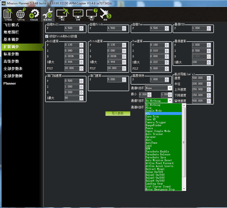
As shown in the image, the auxiliary function switch offers the following options:
1. No action
2. Flip
3. Switch to Simple Mode
4. Return to Launch (RTL) (The aircraft returns to its “home” or starting position; switching back to the low position resumes the mode assigned to CH5)
5. Save changes
6. Save Waypoint (WP)
7. Camera trigger
8. Rangefinder (Disabled in low position, enabled in high position)
9. Geofence (Disabled in low position, enabled in high position)
10. Super Simple Mode
11. Acro (Acrobatic) Mode
12. Sprayer (Disabled in low position, enabled in high position)
13. Auto Mode
14. Auto-tuning Mode
15. Land Mode
16. EPM (Electromagnetic Payload Mechanism)
17. Parachute enable
18. Parachute release
19. Parachute 3-position control (Disabled in low position, automatic in middle position, released in high position)
20. Reset mission
21. AttCon (Attitude Control) feed-forward (For developers only)
22. AttCon (Attitude Control) acceleration limit (For developers only)
23. Retract mount
24. Relay 1 switch (Off in low position, on in high position)
25. Relay 2 switch (Off in low position, on in high position)
26. Relay 3 switch (Off in low position, on in high position)
27. Relay 4 switch (Off in low position, on in high position)
28. Landing gear (Off in low position, on in high position)
29. Fault alarm switch
30. Emergency motor stop
31. Motor interlock
32. Brake (Enabled in high position; switching back to the low position resumes the mode assigned to CH5)
33. Throw (Launch)
34. ADS-B avoidance
35. Precision loiter (hover)
36. Obstacle avoidance
37. Arm/Disarm (Lock/Unlock)
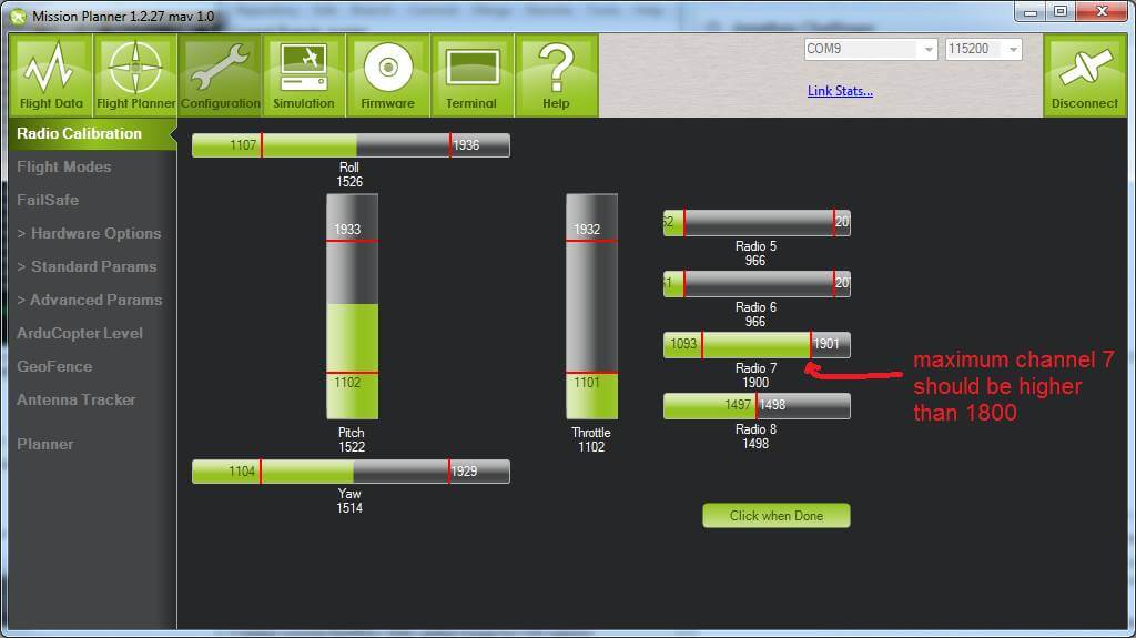
Check whether the PWM values for Ch7 and Ch8 reach 1800
The PWM value for your Channel 7 and/or Channel 8 must reach at least 1800; otherwise, the auxiliary function will not be activated. You can verify whether this threshold has been exceeded by checking the Radio Calibration page in Mission Planner.
Barometer Temperature Compensation
This section demonstrates how to set up function switches that are triggered via auxiliary functions on your transmitter. In AC3.2.1 and earlier versions, channels 7 and 8 could be used as auxiliary switches. This applies to firmware version AC3.3 and later.
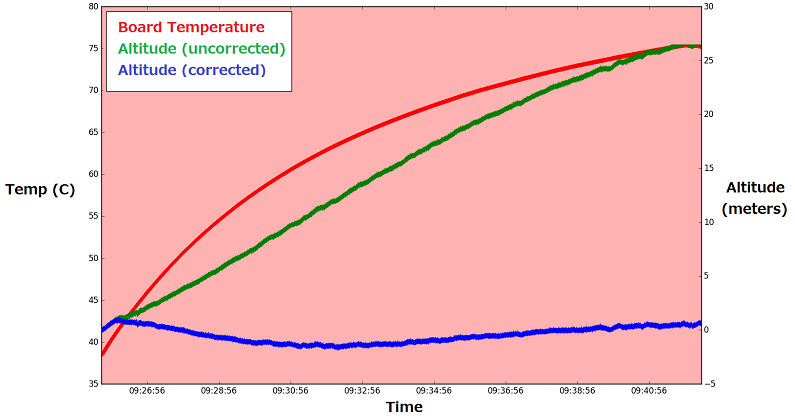
How to use:
- Set TCAL_ENABLE to 2 (to enable learning and use of calibration data).
- Power off the flight controller and allow it to cool down for a few minutes.
- Power on the flight controller and keep it stationary for approximately 10 minutes.
- Once the flight controller has warmed up and remains stationary, the learning process will begin.
- Ensure that the TCAL_BARO_EXP value is set to a non-zero value.
- You can disable the learning process by setting TCAL_ENABLE to 1 (which allows the use of existing calibration data without learning new values).
Boat Mode
Copter 3.4 (and later versions) includes “Boat Mode,” which allows for takeoffs from moving platforms, such as boats. It is not a distinct flight mode in the traditional sense, but rather a modification to how the gyroscopes are calibrated.
“Boat mode” was introduced in Helicopter 3.4
Setup
In many cases, Copter-3.4 can take off from a moving platform without requiring any special parameter adjustments, provided the platform does not move too rapidly during the gyro calibration phase—which occurs in the first few seconds after startup (indicated by flashing red and blue LEDs).
However, if the platform moves excessively, the gyro calibration will fail after 30 seconds, and a warning related to “Bad Gyro Health” will appear on the HUD. While the aircraft might still fly normally despite this warning, the alert is concerning and could potentially mask other errors. In such cases, it is best to disable automatic gyro calibration by setting the `INS_GYR_CAL` parameter to “0”.
Manually Triggering Gyroscope Calibration
Please note that even if automatic gyroscope calibration is disabled, you can still manually trigger it via the “Actions” tab on the “Flight Data” screen in Mission Planner (and potentially other ground control stations). Select “PREFLIGHT_CALIBRATION” from the drop-down menu in the top-left corner, then click the “Do Action” button.
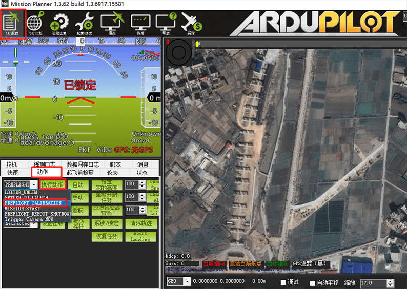
This is useful if, for some reason, a gyroscope calibration is required and the vehicle can be temporarily placed on a nearby, stationary platform.
CAN Bus Configuration
This section describes how to configure the CAN bus and the options that users must select to tailor the setup to their specific requirements.
Overview
Controller Area Network (CAN bus) is a robust bus standard designed to allow microcontrollers and devices to communicate with one another within an application without the need for a host computer. It is a message-based protocol originally developed for multiplexed wiring in automobiles—to reduce the amount of copper required—but it is now used in many other environments as well.
All nodes are interconnected via a two-wire bus, consisting of a 120Ω nominal twisted-pair cable.
Most flight controllers running ArduPilot are equipped with one or more CAN interfaces for connecting various devices. These interfaces can be configured to provide redundancy, maximize throughput, or a combination of both. This is achieved through a three-layered approach: in addition to the physical interface, there is a driver layer representing a specific protocol, and a software layer (ArduPilot) that communicates over the CAN bus via these drivers.
Each physical interface can be virtually connected to a driver representing the protocol to be used. A common configuration, for instance, involves a single driver for the UAVCAN protocol, to which both CAN interfaces are connected. This setup provides redundancy for devices equipped with two CAN interfaces, while ensuring full functionality for devices with a single CAN interface.
Configuration
Enabling CAN Interfaces
Each physical port can be disabled or connected to a corresponding driver via the `CAN_PX_DRIVER` parameter, where `X` represents the port number. The value of this parameter is the ID of the driver to be associated with that port (interface).
For example, a common setup involves a single driver to which all interfaces are connected. In this configuration, the `CAN_P1_DRIVER` and `CAN_P2_DRIVER` parameters should both be set to 1 (referring to the first driver).

After changing CAN_PX_DRIVER, the autopilot must be restarted.
Configuring CAN Interfaces
Once an interface has been enabled and the system has been restarted, two additional parameters can be configured for each enabled interface:
These are:
CAN_PX_BITRATE – Sets the desired bit rate for the interface.
CAN_PX_DEBUG – Enables the output of debug messages.
The default bit rate is typically 1 Mbit/s. The debug level can be adjusted according to the user’s preferences and requirements.

Configuring CAN Interfaces
Once an interface has been enabled and the system has been restarted, two additional parameters can be configured for each enabled interface:
These are:
CAN_PX_BITRATE – Sets the desired bit rate for the interface.
CAN_PX_DEBUG – Enables the output of debug messages.
The default bit rate is typically 1 Mbit/s. The debug level can be adjusted according to the user’s preferences and requirements.

Configuring CAN Drivers
Drivers must be configured to use specific protocols. Currently, UAVCAN (designated as protocol 1) is supported. The parameter `CAN_PX_PROTOCOL`—where `X` represents the driver number—should be set to the corresponding protocol number.
Advanced Compass Setup
This section provides advanced guidance on setting up and calibrating a compass (magnetometer).
Users who select the 3DR UBlox GPS + Compass module (recommended) and install it according to the provided instructions can generally perform a simple “live calibration” (as described in the “Compass Calibration” section of the Compass Calibration page).
This topic offers a more comprehensive overview of compass calibration. It is particularly useful if the compass is installed in a non-standard orientation or if additional calibration support is required.
Overview
Accurate compass configuration is critical, as it serves as the primary source of heading information. Without an accurate heading, the vehicle will not move in the correct direction when operating in autonomous modes (e.g., AUTO, LOITER, PosHold, RTL, etc.). This can lead to issues such as “toilet-bowling” (circling) or a loss of control resulting in a crash.
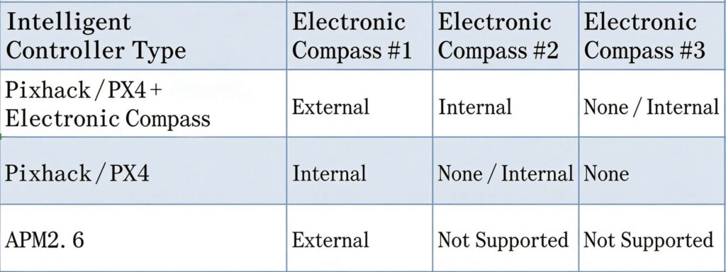
ArduPilot currently supports the use of up to three compasses. Only one compass—designated via the `COMPASS_PRIMARY` parameter (with compass #1 set as the primary by default)—is used for navigation. While many autopilot boards include an internal compass, most setups utilize an external one; because it is physically separated from other electronic components, the data it provides is more reliable than that of an internal compass.
The standard configuration for common autopilot boards is shown in the table below:
Configuration Settings
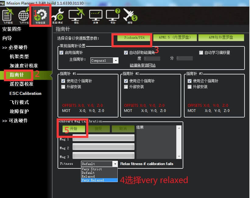
Firmware versions AC 3.4 and later support on-board compass calibration. When used with Ground Control Station (GCS) software version 1.3.46 or higher, the GCS will automatically disable the field calibration interface and mandate the use of on-board compass calibration. According to available documentation and practical testing, on-board compass calibration is more reliable than field calibration. The following section describes the on-board compass calibration process:
Quick Configuration
The ground station supports automatic configuration for all parameters of the most common autopilot boards. Simply select the button that corresponds to your specific autopilot:
For Pixhawk and PX4, select the “Pixhawk / PX4” button. You may be prompted to specify the ArduPilot version you are using.
For APM 2.6 (with an external compass), select “APM.”
For APM 2.5 (with an internal compass), select “APM (Internal Compass).”
If your external compass is mounted in a non-standard orientation, you must manually select the correct orientation from the drop-down menu (changing it from the default “ROTATION_NONE”). Note that the external compass orientation setting (COMPASS_ORIENT) is independent of the AHRS orientation parameter (AHRS_ORIENTATION).
For the “Fitness” option, selecting “Very Relaxed” is recommended for most users, as this makes the calibration process easier to complete successfully.
Verifying Compass Orientation
Ensuring the AHRS_ORIENTATION parameter is set correctly guarantees that your onboard compass is oriented properly.
When you rotate your aircraft along any axis, the values for each compass should move in the same direction and remain roughly consistent with one another.
- Northern Hemisphere: With the compass facing upward, the Z-axis value should be positive; as the autopilot tilts downward (nose down), the X-axis value should increase; as the autopilot turns to the right, the Y-axis value should increase.
- Southern Hemisphere: With the compass facing upward, the Z-axis value should be negative; as the autopilot tilts downward (nose down), the X-axis value should decrease; as the autopilot turns to the right, the Y-axis value should decrease.
General Settings
These general settings apply to all compasses connected to the autopilot controller:
Enable Compass: Determines whether any compass is enabled. If enabled, the flight controller will use the primary compass for heading data; otherwise, the heading will be estimated from GPS. Enabling this checkbox corresponds to the parameter setting MAG_ENABLE = 1.
Primary Compass: Specifies which compass ArduPilot uses for navigation (only one compass is used for navigation). By default, this is usually the first compass (“Compass1”). This selection corresponds to the parameter COMPASS_PRIMARY, which can be set to a value from 0 to 2 (corresponding to items 1 through 3 in the interface; note that the internal indexing for compasses begins at 0).
Auto-detect Declination: Automatically sets the magnetic declination based on a lookup table once a GPS lock is acquired. Users may also modify this value; by unchecking the box (setting COMPASS_AUTODEC = 0), you can manually enter the declination in the COMPASS_DEC parameter.
Compass-Specific Settings
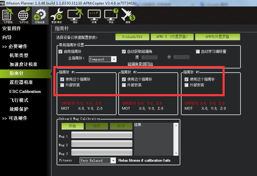
In the compass calibration interface, you can select any combination of compasses to use.
- Use this compass: Check the box to enable a specific compass; uncheck it to disable it. This corresponds to the `COMPASS_USEx` parameter (where x is 0–2).
- Externally mounted compass: Indicates whether a compass is mounted externally. For an external compass, set `COMPASS_EXTERNAL=1`. If it is an internal compass, its orientation is determined by `AHRS_ORIENTATION`. An external compass may have a different heading orientation than the flight controller’s internal compass.
- Compass orientation: Defines the mounting orientation of an external compass; this value is saved to the `COMPASS_ORIENTx` parameter.
The `OFFSETS` (`COMPASS_OFFSx`) and `MOT` (`COMPASS_MOT`) parameters are populated via real-time calibration and the `CompassMot` procedure (see the calibration section below).
CompassMot – Compensating for interference from power wires, the ESC, and motors
This feature is recommended for flight controllers that rely solely on an internal compass, especially when the motor power wires cause significant magnetic interference. A battery current monitor is required for CompassMot to function, as there is a linear relationship between magnetic interference and electrical current. While it is technically possible to configure CompassMot based on throttle position, this is not recommended.
Please follow the instructions below:
- Enable the voltage and current monitor.
- Install the propellers upside down (reversed) so that, even if the throttle is increased, the thrust generated pushes the aircraft downward, preventing it from taking off.
- Secure the aircraft firmly in place so it cannot move.
- Turn on your remote control (transmitter).
- Connect the battery to power the flight controller.
- Connect the flight controller to your computer’s ground station software via a USB cable.
If you are using AC3.2:
Navigate to Initial Setup | Optional Hardware | Compass/Motor Calibration.
Click the “Start” button.
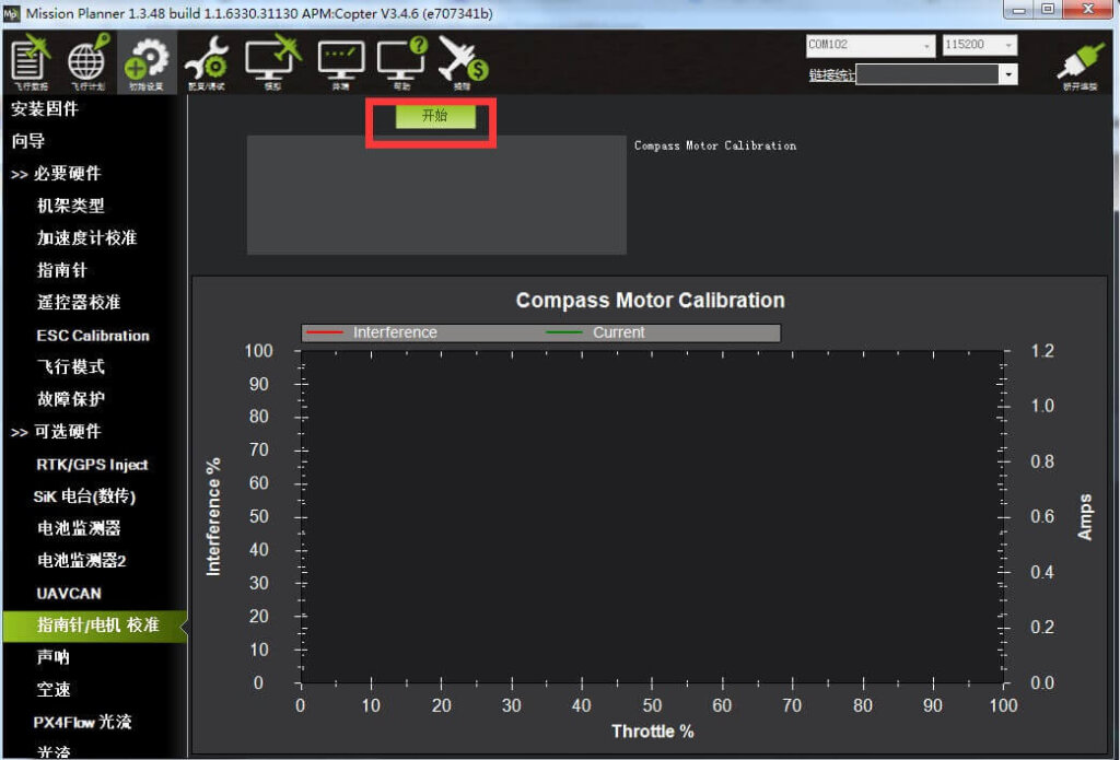
You should hear two beeps.
Slowly increase the throttle to 50%–75% (the aircraft will spin!) for 5–10 seconds.
Quickly return the throttle to zero.
Press the “Done” button (in AC3.2) to complete the calibration.
Check the displayed interference percentage. If it is less than 30%, the interference to your compass is acceptable, and you should see good performance in Loiter, RTL, and AUTO modes. If it is higher than 30%, you should try moving the APM/PX further away from the source of interference, or consider purchasing an external compass (or a GPS + compass module).
Compass Error Alerts
- Compass Health: The compass has failed to send at least one signal within a half-second interval.
- Compass Variance: The Kalman filter has detected an inconsistency; the discrepancy between multiple compasses is too large (e.g., a difference greater than 100 on the X or Y axes, or an inverted Z-axis).
- Compass Not Calibrated: The compass has not been calibrated.
- Compass Offsets High: The offset value for one of your compasses exceeds 600, which may indicate magnetic interference. Please check for sources of interference and recalibrate.
Triggering compass calibration via the remote controller
This feature was introduced in AC3.4.
ArduPilot supports triggering compass calibration via your remote controller, eliminating the need to connect to a ground control station. Simply follow these steps:
- Ensure that a buzzer and a safety switch are installed.
- Move both the throttle stick and the yaw (rudder) stick to their maximum positions and hold them there for 3 seconds. Once the buzzer begins to emit a series of beeps, the system has entered the compass calibration mode.
- Rotate the drone until the audible tones stop; this indicates that the calibration is complete.
Current Limiting and Voltage Regulation
The DC motor system includes current limiting to protect the battery from damage, as well as voltage regulation to compensate for the voltage drop that occurs as the battery depletes. Both of these features require the drone to be equipped with a power module or some other form of voltage and current monitor.
Current limiting and voltage regulation were introduced in Copter 3.3.
Current Limiting
This protection feature automatically reduces the throttle to 60% of its full range, thereby limiting the current drawn from the battery. It can be used to protect the battery from damage.
To enable this feature, set the `MOT_CURR_MAX` parameter to the desired current limit in amperes (or set it to “0” to disable the feature).
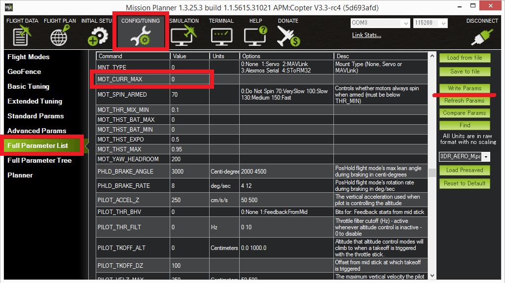
If the measured current exceeds this limit at maximum throttle for 1 to 5 seconds, it will be reduced to a safe level. Since the limit can be exceeded for short periods, the time threshold should be set based on the battery’s burst rating, which serves as the absolute upper limit.
Voltage Scaling
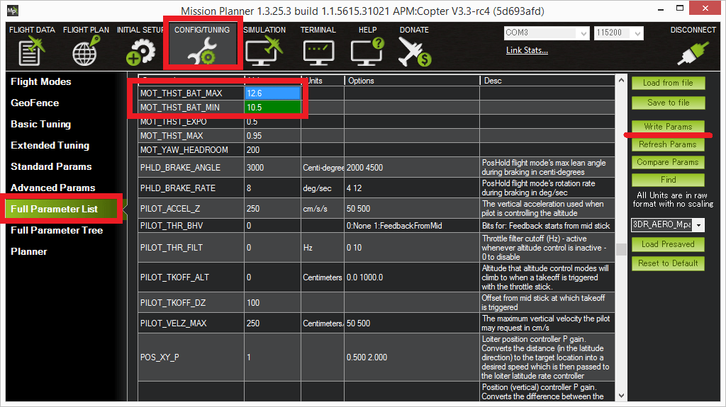
When enabled, this feature increases the control gains for roll, pitch, and yaw to compensate for the voltage drop that occurs as the battery discharges. This helps ensure that the drone’s attitude control performance does not degrade as the battery power wanes. To enable this, set `MOT_THST_BAT_MAX` to the fully charged voltage of your battery (e.g., 12.6V for a 3S battery). The gains will be scaled to maintain an attitude control response similar to that of a fully charged battery. Set `MOT_THST_BAT_MIN` to the minimum battery voltage typically encountered during operation; the gains will stop scaling once the voltage drops below this level. A good starting point is to set this value to your battery failsafe voltage.
Extended Kalman Filter (EKF)
Helicopters and fixed-wing aircraft can utilize the Extended Kalman Filter (EKF) algorithm to estimate their position, velocity, and orientation (attitude) by fusing data from rate gyroscopes, accelerometers, compasses, GPS, airspeed sensors, and barometric pressure sensors.
Compared to simpler complementary filter algorithms (often referred to as “inertial navigation”), the EKF offers the advantage of integrating all available measurement data. This allows it to effectively filter out erroneous readings, ensuring that the aircraft remains resilient to the failure of any single sensor. The EKF can also incorporate data from optional sensors—such as optical flow sensors and laser rangefinders—to further assist with navigation.
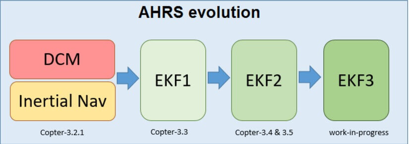
In the current stable version of ArduPilot, EKF2 serves as the primary source for attitude and position estimation, while the Direction Cosine Matrix (DCM) algorithm runs in the background. If a flight controller is equipped with two (or more) IMUs, the system will run two EKF “cores” (instances) in parallel, with each core utilizing a different IMU. The flight controller then selects the EKF core that demonstrates the best data consistency and performance to serve as the primary output, while the other cores remain inactive in terms of output.
Most users do not need to modify any EKF parameters; however, the information below covers some of the most common adjustments. Further details can be found on the EKF wiki page for developers.
Selecting EKF and Number of Cores
AHRS_EKF_USE: Set to “1” to enable the EKF. In Copter-3.2.1, it is used for attitude control and inertial navigation, or for heading estimation (dead reckoning) in position control. In Copter-3.3 (and later versions), this parameter is forced to “1” and cannot be changed.
AHRS_EKF_TYPE: Set to “2” to use EKF2 for attitude and position estimation, or to “3” to use EKF3.
EK2_ENABLE, EK3_ENABLE: Set to “1” to enable EKF2 and EKF3, respectively.
EK2_IMU_MASK, EK3_IMU_MASK: A bitmask specifying which IMUs (i.e., accelerometers/gyroscopes) to use. An EKF “core” (an individual EKF instance) will be launched for each specified IMU.
1: Launch a single EKF core using the first IMU.
2: Launch a single EKF core using only the second IMU.
3: Launch two separate EKF cores, using the first and second IMUs, respectively.
Common Parameter Modifications
EK2_ALT_SOURCE: Determines which sensor is used as the primary altitude source.
0: Use barometer (default).
1: Use rangefinder. This can be used in environments where barometer data is very noisy and the ground is relatively flat (e.g., indoors, where air conditioning might cause sudden pressure fluctuations). It should not be used if the intention is to perform terrain following. For terrain-following operations, please refer to the specific instructions for helicopters and fixed-wing aircraft.
2: Use GPS. Useful when GPS quality is very high and barometer drift could be an issue—for example, during long-range missions where the aircraft will undergo altitude changes greater than 100m.
EK2_ALT_NOISE: Default value is “1.0”. A lower value reduces reliance on the accelerometer and increases reliance on the barometer.
EK2_GPS_TYPE: Controls how GPS data is utilized.
0: Use 3D velocity and 2D position from GPS.
1: Use 2D velocity and 2D position (GPS velocity is not used for altitude estimation).
2: Use 2D position.
3: No GPS (uses optical flow only, if available).
A more detailed overview of EKF theory and tuning parameters can be found in the “Extended Kalman Filter Navigation Overview and Tuning” section of the developer wiki.
Ground Effect Compensation
Copter 3.4 (and later versions) includes ground effect compensation, which reduces the weight given to the barometer (favoring the accelerometer instead) during takeoff or landing. This helps minimize bouncing when the aircraft touches down.
If your aircraft does not bounce upon landing, it is best to disable this feature, as it slightly increases the risk that altitude vibrations could disrupt altitude estimation.
Configuration
Connect the flight controller to a ground station (such as Mission Planner) and set the `GND_EFFECT_COMP` parameter to “1”.
Flight Time Recorder
Copter-3.5 (and later versions) includes a flight-time logger that records total flight time, total runtime, and the number of flight controller reboots. These values are stored in user-resettable parameters, meaning they are not protected against tampering.
Parameter Details
STAT_BOOTCNT: Stores the number of times the flight controller has booted.
STAT_FLTTIME: Stores the total number of seconds the flight controller/vehicle has spent in flight (including all previous flights).
STAT_RUNTIME: Stores the total number of seconds the flight controller has been powered on (including all previous flights).
STAT_RESET: Stores the timestamp (in seconds since the Unix epoch—January 1, 1970) of when the statistics were last reset. If a GPS providing real-time data is connected, this value will reflect the actual time; otherwise, it will be close to January 1, 1970. Users can trigger a reset of all statistics by setting this parameter to “0” Once set to 0, the parameter will immediately update to the current time (seconds since the epoch), and all other statistics parameters will be reset to zero.
When are these counters reset?
Upgrading or downgrading the firmware version for a specific vehicle type does not clear these STAT parameters (e.g., upgrading from Copter-3.4 to 3.5 will not clear them).
Because these parameters are not protected, users can modify them. Additionally, they may be reset in the following scenarios:
Loading firmware for a different vehicle type onto the flight controller (e.g., flashing Copter firmware onto a board that was previously running Plane firmware).
The user performs a manual parameter reset.
Motor Thrust Expansion
The helicopter firmware includes motor thrust scaling, which compensates for the non-linear thrust output characteristic of most ESCs and motors.
Note:
The default curves are suitable for almost all ESC/motor combinations; generally, these parameters should not be adjusted unless the actual thrust curve of the aircraft has been measured.
Motor thrust scaling was introduced in helicopter firmware version 3.3.
Thrust Curve
The curve is defined by two parameters:
- `MOT_THST_EXPO` controls the shape of the thrust curve: a value of “0” results in a perfectly linear curve, while “1.0” produces a highly curved (non-linear) response (see the image below).
The default value is “0.65” (note that the image below incorrectly shows the default value as 0.5).
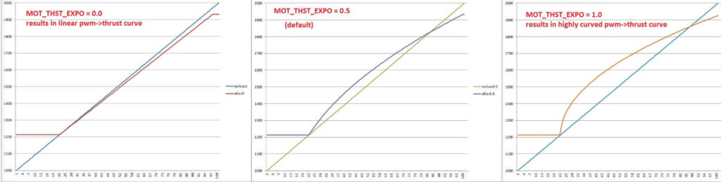
- `MOT_THST_MAX` controls the point at which the thrust levels off near its maximum value. The default value is 0.95, representing 95% of the throttle.
MATLAB Example Code
This MATLAB example code can be used to calculate the appropriate value for `MOT_THST_EXPO` based on measured thrust values.
Populate the thrust array with the actual measured thrust values from your aircraft. When the code is run, it will output the `MOT_THST_EXPO` value.
Code: http://ardupilot.org/copter/docs/motor-thrust-scaling.html
The content above provides a tutorial on the settings required for the first flight of a multi-rotor aircraft. Please stay tuned for the next article:
《Advanced Settings for Multi-rotor Aircraft-Ⅱ》

Purchase Channels
CUAV Downloads
Products Brochure
Product Usage Scope and Limitations